184
[SwitchD] isis 1
[SwitchD-isis-1] domain-authentication-mode md5 plain 1020Sec
IS-IS GR configuration example
Network requirements
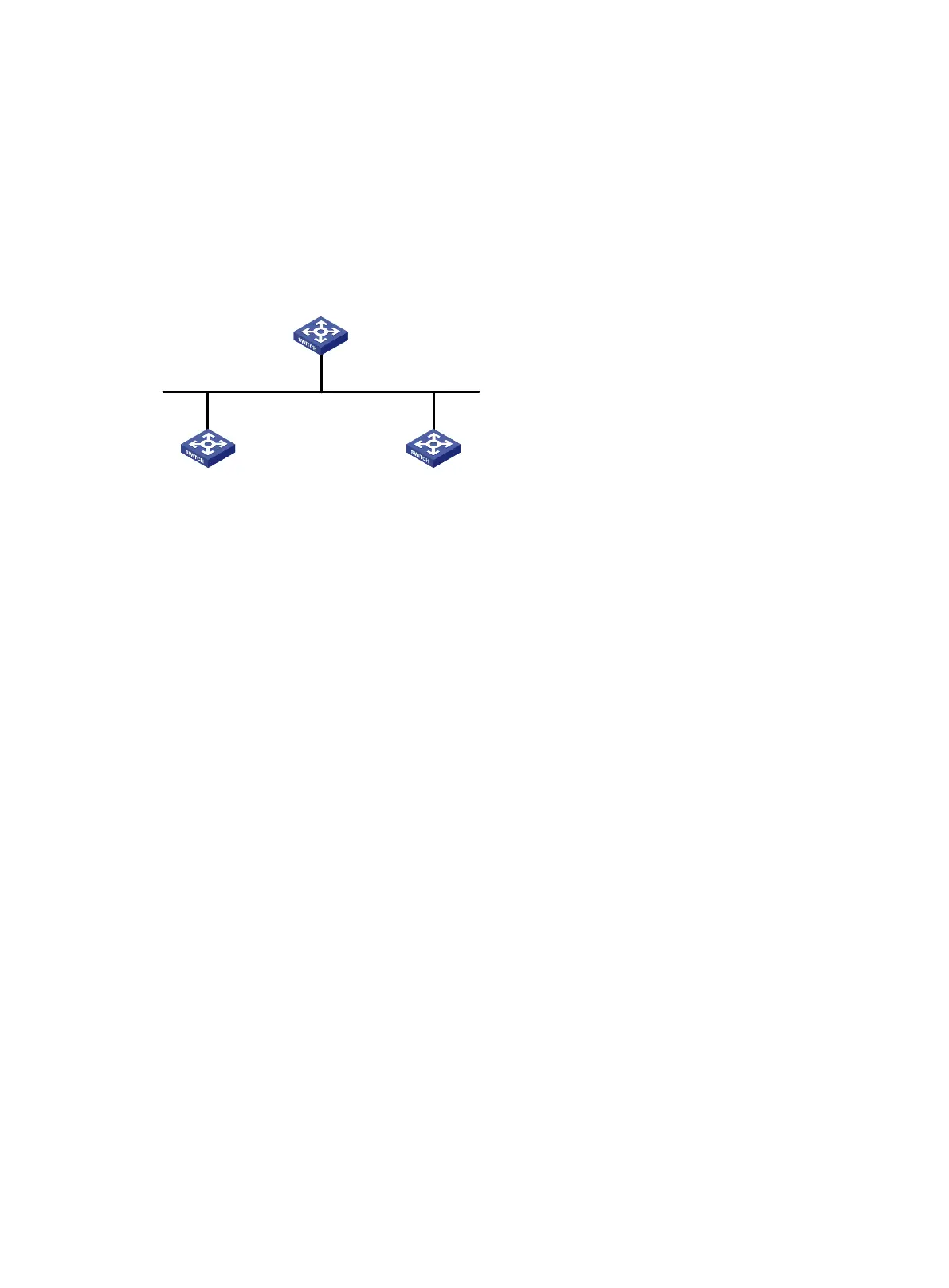
As shown in Figure 47, Switch A, Switch B, and Switch C belong to the same IS-IS routing domain.
Figure 47 Network diagram
Configuration procedure
1. Configure IP addresses and subnet masks for interfaces. (Details not shown.)
2. Configure IS-IS on the switches to make sure Switch A, Switch B, and Switch C can
communicate with each other at layer 3 and dynamic route update can be implemented among
them with IS-IS. (Details not shown.)
3. Enable IS-IS GR on Switch A.
<SwitchA> system-view
[SwitchA] isis 1
[SwitchA-isis-1] graceful-restart
[SwitchA-isis-1] return
Verifying the configuration
# Restart the IS-IS process on Switch A.
<SwitchA> reset isis all 1 graceful-restart
Reset IS-IS process? [Y/N]:y
# Check the GR state of the IS-IS process on Switch A.
<SwitchA> display isis graceful-restart status
Restart information for IS-IS(1)
--------------------------------
Restart status: COMPLETE
Restart phase: Finish
Restart t1: 3, count 10; Restart t2: 60; Restart t3: 300
SA Bit: supported
Level-1 restart information
---------------------------
Total number of interfaces: 1
Number of waiting LSPs: 0
Vlan
-int
100
10
.0
.0
.
1/
24
Vlan-
int100
10
.
0.
0
.3
/24
Vlan-
int100
10
.
0.
0.
2
/24
GR helper GR helper
GR restarter
Switch A
Switch C
Switch B
 Loading...


