498
(In IRF mode.) Display IPv6 local PBR
configuration and statistics.
display ipv6 policy-based-route local
[
chassis
chassis-number
slot-number ]
(In standalone mode.) Display IPv6 interface
PBR configuration and statistics.
display ipv6 policy-based-route interface
interface-type
interface-number [
slot
slot-number ]
(In IRF mode.) Display IPv6 interface PBR
configuration and statistics.
display ipv6 policy-based-route interface
interface-type
interface-number [
chassis
chassis-number
slot
slot-number ]
Clear IPv6 PBR statistics.
reset ipv6 policy-based-route statistics
[
policy
policy-name
]
IPv6 PBR configuration examples
Packet type-based IPv6 local PBR configuration example
Network requirements
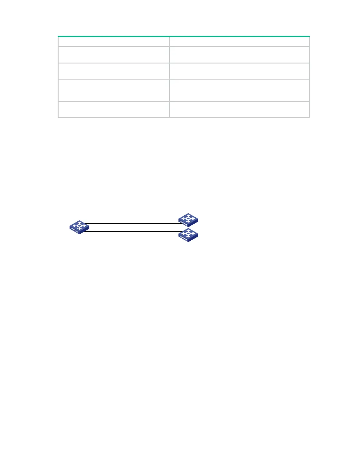
As shown in Figure 115, configure IPv6 PBR on Switch A to forward all TCP packets to the next hop
1::2. Switch A forwards other packets according to the routing table.
Figure 115 Network diagram
Configuration procedure
1. Configure Switch A:
# Create VLAN 10 and VLAN 20.
<SwitchA> system-view
[SwitchA] vlan 10
[SwitchA-vlan10] quit
[SwitchA] vlan 20
[SwitchA-vlan20] quit
# Configure the IPv6 addresses of VLAN-interface 10 and VLAN-interface 20.
[SwitchA] interface vlan-interface 10
[SwitchA-Vlan-interface10] ipv6 address 1::1 64
[SwitchA-Vlan-interface10] quit
[SwitchA] interface vlan-interface 20
[SwitchA-Vlan-interface20] ipv6 address 2::1 64
[SwitchA-Vlan-interface20] quit
# Configure ACL 3001 to match TCP packets.
[SwitchA] acl ipv6 advanced 3001
[SwitchA-acl-ipv6-adv-3001] rule permit tcp
[SwitchA-acl-ipv6-adv-3001] quit
# Configure Node 5 for policy aaa to forward TCP packets to next hop 1::2.
Switch A
Switch B
Switch C
Vlan-int20
2::1/64
Vlan-int10
1::1/64
Vlan-int20
2::2/64
Vlan-int10
1::2/64
 Loading...


