345
BFD for BGP configuration example
Network requirements
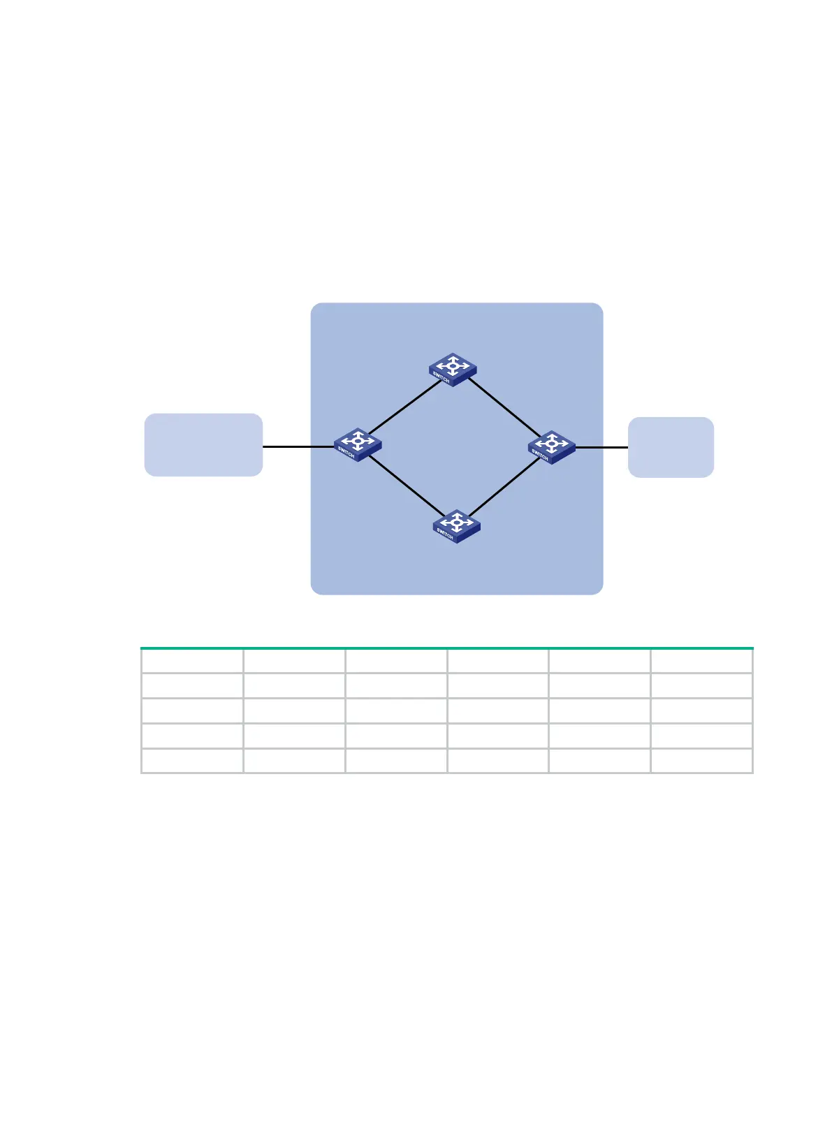
As shown in Figure 77, configure OSPF as the IGP in AS 200.
Establish two IBGP connections between Switch A and Switch C. When both paths operate
correctly, Switch C uses the path Switch A<—>Switch B<—>Switch C to exchange packets
with network 1.1.1.0/24.
Configure BFD over the path. When the path fails, BFD can quickly detect the failure and notify
it to BGP. Then, the path Switch A<—>Switch D<—>Switch C takes effect immediately.
Figure 77 Network diagram
Table 19 Interface and IP address assignment
Switch A Vlan-int100 3.0.1.1/24 Switch C Vlan-int101 3.0.2.2/24
Vlan-int200 2.0.1.1/24 Vlan-int201 2.0.2.2/24
Switch B Vlan-int100 3.0.1.2/24 Switch D Vlan-int200 2.0.1.2/24
Vlan-int101 3.0.2.1/24 Vlan-int201 2.0.2.1/24
Configuration procedure
1. Configure IP addresses for interfaces. (Details not shown.)
2. Configure OSPF to ensure that Switch A and Switch C are reachable to each other. (Details not
shown.)
3. Configure BGP on Switch A:
# Establish two IBGP connections to Switch C.
<SwitchA> system-view
[SwitchA] bgp 200
[SwitchA-bgp-default] peer 3.0.2.2 as-number 200
[SwitchA-bgp-default] peer 2.0.2.2 as-number 200
[SwitchA-bgp-default] address-family ipv4 unicast
[SwitchA-bgp-default-ipv4] peer 3.0.2.2 enable
Switch A Switch C
AS 200
Switch D
Vlan-int200
Vlan-int201
Switch B
AS 300
Vlan-int101Vlan-int100
Vlan-int100
Vlan-int101
Vlan-int200
Vlan-int201
AS 100
1.1.1.0/24
 Loading...


