490
Destination IP: FE80::20F:FF:FE00:1200 (link-local address of VLAN-interface 10 on
Switch B)
Session State: Up Interface: Vlan10
Hold Time: 2319ms
# Display routes destined for 2001:4::0/64 on Switch A.
<SwitchA> display ipv6 routing-table 2001:4::0 64
Summary Count : 1
Destination: 2001:4::/64 Protocol : IS_L1
NextHop : FE80::20F:FF:FE00:1200 Preference: 15
Interface : Vlan10 Cost : 10
The output shows that Switch A and Switch B communicate through VLAN-interface 10. Then the
link over VLAN-interface 10 fails.
# Display routes destined for 2001:4::0/64 on Switch A.
<SwitchA> display ipv6 routing-table 2001:4::0 64
Summary Count : 1
Destination: 2001:4::/64 Protocol : IS_L1
NextHop : FE80::BAAF:67FF:FE27:DCD0 Preference: 15
Interface : Vlan11 Cost : 20
The output shows that Switch A and Switch B communicate through VLAN-interface 11.
IPv6 IS-IS FRR configuration example
Network requirements
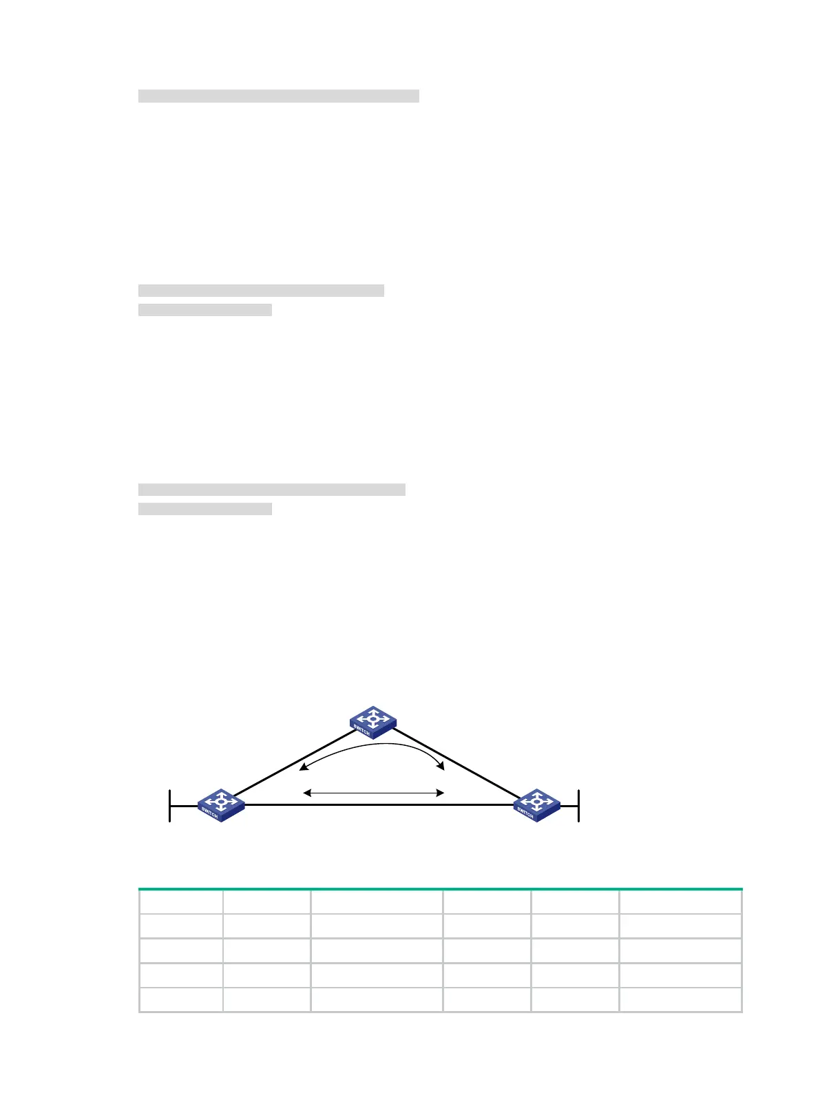
As shown in Figure 114, Switch A, Switch B, and Switch C belong to the same IS-IS routing domain.
Configure IPv6 IS-IS FRR so that when the Link A fails, traffic can be switched to Link B immediately.
Figure 114 Network diagram
Table 29 Interface and IP address assignment
Switch A Vlan-int100 1::1/64 Switch B Vlan-int101 3::1/64
Vlan-int200 2::1/64 Vlan-int200 2::2/64
Loop0 10::1/128 Loop0 20::1/128
Switch C Vlan-int100 1::2/64
Switch A Switch B
Switch C
Loop0
Vlan-int100
Vlan-int200
Vlan-int200
Vlan-int100
Vlan-int101
Vlan-int101
Loop0
Link A
Link B
 Loading...


