449
Display OSPFv3 next hop
information.
display
ospfv3
[ process-id ]
nexthop
Display OSPFv3 neighbor
information.
display ospfv3
[ process-id ] [
area
area-id ]
peer
[ [ interface-type
interface-number ] [
verbose
] | peer-router-id |
statistics
]
Display OSPFv3 request list
information.
display ospfv3
[ process-id ] [
area
area-id ]
request-queue
[ interface-type interface-number ] [ neighbor-id ]
Display OSPFv3 retransmission list
information.
display ospfv3
[ process-id ] [
area
area-id ]
retrans-queue
[ interface-type interface-number ] [ neighbor-id ]
Display OSPFv3 routing information.
display ospfv3
[ process-id ]
routing
[ ipv6-address
prefix-length ]
Display OSPFv3 topology
information.
display
ospfv3
[ process-id ] [
area
area-id ]
spf-tree
[
verbose
]
Display OSPFv3 statistics.
display ospfv3
[ process-id ]
statistics
[
error
]
Display OSPFv3 virtual link
information.
display ospfv3
[ process-id ]
vlink
Clear OSPFv3 log information.
reset ospfv3
[ process-id ]
event-log
[
lsa-flush
|
peer
|
spf
]
Restart an OSPFv3 process.
reset
ospfv3
[ process-id ]
process
[
graceful-restart
]
Restart OSPFv3 route redistribution.
reset
ospfv3
[ process-id ]
redistribution
Clear OSPFv3 statistics.
reset ospfv3
[ process-id ]
statistics
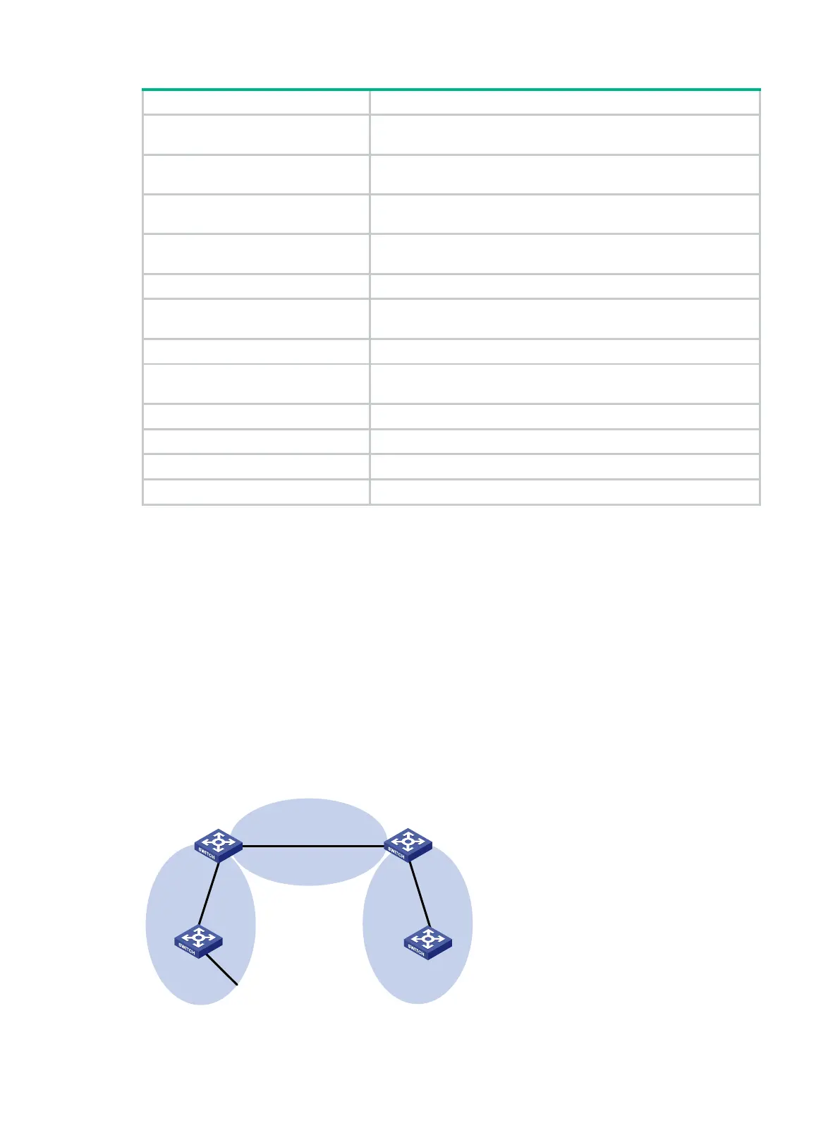
OSPFv3 configuration examples
OSPFv3 stub area configuration example
Network requirements
As shown in Figure 101:
Enable OSPFv3 on all switches.
Split the AS into three areas.
Configure Switch B and Switch C as ABRs to forward routing information between areas.
Configure Area 2 as a stub area to reduce LSAs in the area without affecting route reachability.
Figure 101 Network diagram
OSPFv
3
Area 0
OSPFv3
Area 1
OSPFv3
Area 2
Switch A
Vlan-int100
2001::2/64
Vlan-int100
2001::
1/64
Vlan-int3
00
2001:
3::1/64
Vlan
-int200
2001:1::2/64
Switch C
Vlan-int
400
2001:2
::1/64
Vlan-int4
00
2001
:2::2/64
Switch B
Vlan-int200
2001:1::1/64
Switch D
 Loading...


