519
DCN configuration examples
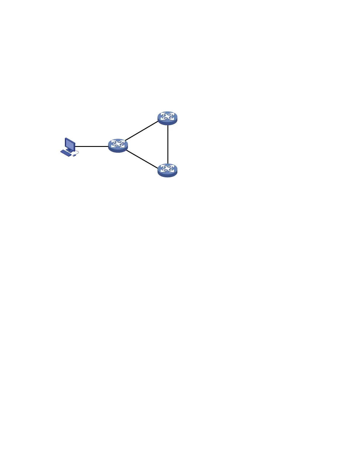
Network requirements
As shown in Figure 119, the GNE, Device A, and Device B run DCN in the same VPN instance. The
NMS uses SNMP to manage the GNE, and the GNE automatically sends notifications to the NMS to
report online or offline events of NEs.
Figure 119 Network diagram
Configuration procedure
1. Configure the GNE:
# Enable SNMP on the GNE. (Details not shown. For more information, see Network
Management and Monitoring Configuration Guide.)
# Enable DCN, configure the NE ID as 100001 and NE IP as 11.1.1.1/32, and enable the
automatic report feature.
<GNE> system-view
[GNE] dcn
[GNE-dcn] ne-id 100001
[GNE-dcn] ne-ip 11.1.1.1 32
[GNE-dcn] auto-report
[GNE-dcn] quit
# Create a VPN instance named dcn_vpn.
[GNE] ip vpn-instance dcn_vpn
[GNE-vpn-instance-dcn_vpn] quit
# Create interface Loopback 1023, and associate it with VPN instance dcn_vpn.
[GNE] interface loopback 1023
[GNE-LoopBack1023] ip binding vpn-instance dcn_vpn
[GNE-LoopBack1023] quit
# Enable LLDP globally.
[GNE] lldp global enable
# Enable the nearest bridge agents on GigabitEthernet 1/0/1 to advertise basic LLDP TLVs and
management address TLVs. The IP address of interface Loopback 1023 is specified as the
management address.
[GNE] interface gigabitethernet 1/0/1
[GNE-GigabitEthernet1/0/1] port link-mode route
[GNE-GigabitEthernet1/0/1] lldp tlv-enable basic-tlv management-address-tlv
interface loopback 1023
GE1/0/1
GE1/0/2
GE1/0/1
GE1/0/2
GE1/0/1
GE1/0/2
GNE
Device B
Device A
NMS
 Loading...


