358
BGP LS configuration example
Network requirements
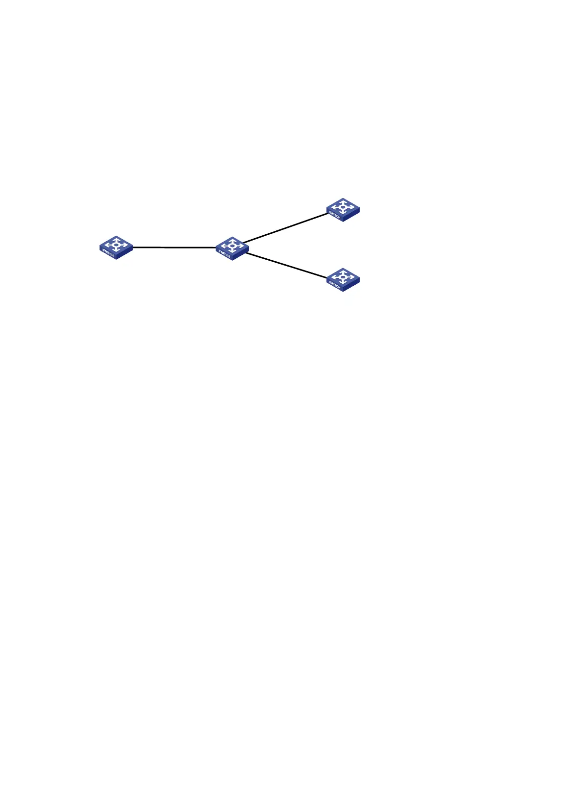
As shown in Figure 81, all switches run BGP. Run IBGP between Switch A and Switch B, between
Switch B and Switch C, and between Switch B and Switch D.
Configure Switch B as a route reflector with client Switch A to allow Switch A to learn LS information
advertised by Switch C and Switch D.
Figure 81 Network diagram
Configuration procedure
1. Configure IP addresses for interfaces and configure OSPF on Switch C and Switch D. (Details
not shown.)
2. Configure BGP connections:
# Configure Switch A.
<SwitchA> system-view
[SwitchA] bgp 100
[SwitchA-bgp-default] peer 192.1.1.2 as-number 100
[SwitchA-bgp-default] address-family link-state
[SwitchA-bgp-default-ls] peer 192.1.1.2 enable
[SwitchA-bgp-default-ls] quit
[SwitchA-bgp-default] quit
# Configure Switch B.
<SwitchB> system-view
[SwitchB] bgp 100
[SwitchB-bgp-default] peer 192.1.1.1 as-number 100
[SwitchB-bgp-default] peer 193.1.1.1 as-number 100
[SwitchB-bgp-default] peer 194.1.1.1 as-number 100
[SwitchB-bgp-default] address-family link-state
[SwitchB-bgp-default-ls] peer 192.1.1.1 enable
[SwitchB-bgp-default-ls] peer 193.1.1.1 enable
[SwitchB-bgp-default-ls] peer 194.1.1.1 enable
[SwitchB-bgp-default-ls] quit
[SwitchB-bgp-default] quit
# Configure Switch C.
<SwitchC> system-view
[SwitchC] bgp 100
[SwitchC-bgp-default] peer 193.1.1.2 as-number 100
[SwitchC-bgp-default] address-family link-state
Vlan-
int11
192.
1.
1
.1
/2
4
Switch A
Switch B
Vlan-
int11
192.
1.
1
.2
/24
Switch
C
Switch
D
Vlan
-int12
193.1.1.1/24
Vlan-int12
193.1.1.2/24
Vlan-int13
194.1.1.2/24
Vlan-int13
194.1.1.1/24
 Loading...


