454
OSPFv3 NSSA area configuration example
Network requirements
As shown in Figure 102:
Configure OSPFv3 on all switches and split the AS into three areas.
Configure Switch B and Switch C as ABRs to forward routing information between areas.
Configure Area 1 as an NSSA area and configure Switch A as an ASBR to redistribute static
routes into the AS.
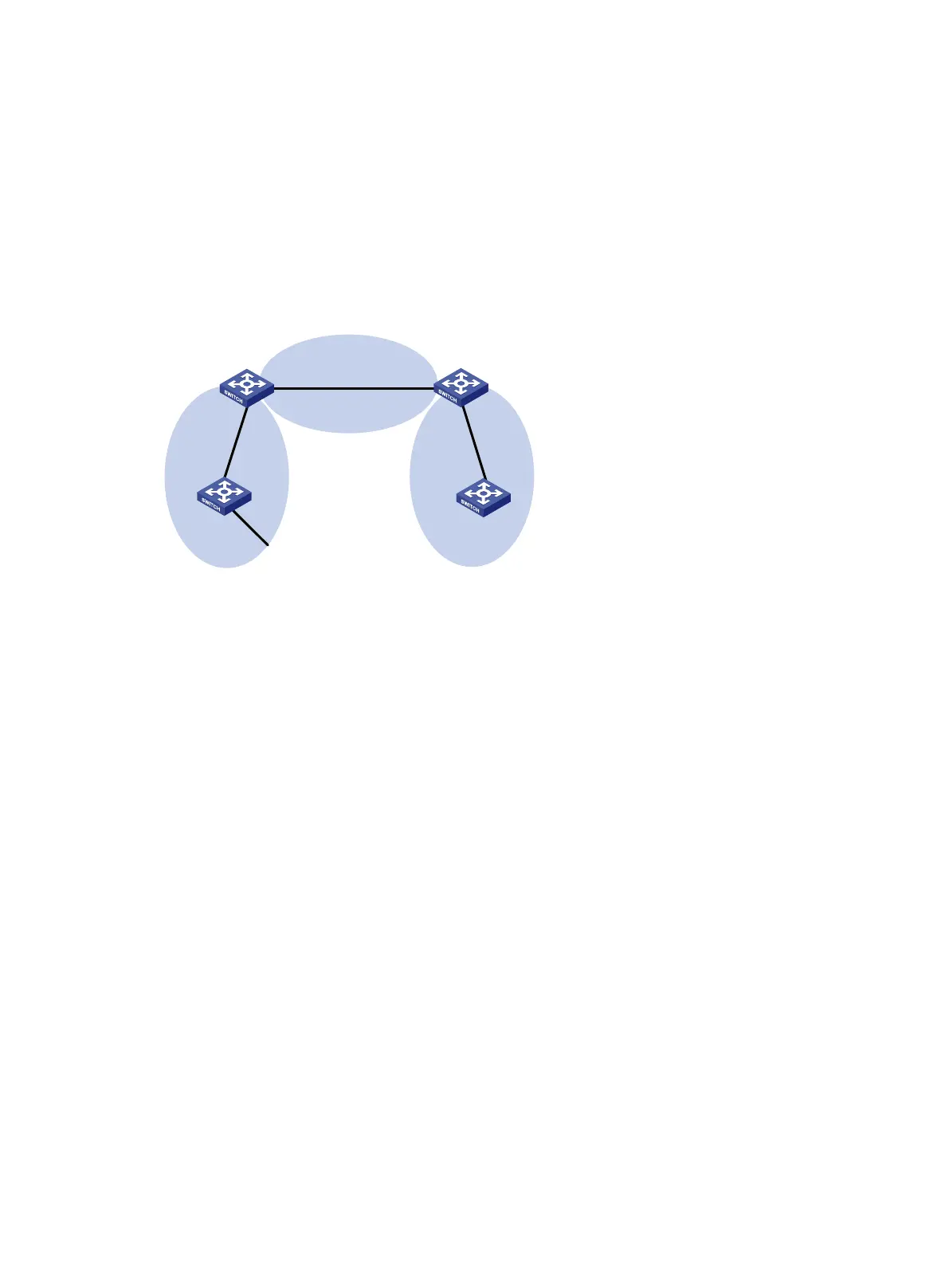
Figure 102 Network diagram
Configuration procedure
1. Configure IPv6 addresses for interfaces. (Details not shown.)
2. Configure basic OSPFv3 (see "OSPFv3 stub area configuration example").
3. Configure Area 1 as an NSSA area:
# Configure Switch A.
[SwitchA] ospfv3
[SwitchA-ospfv3-1] area 1
[SwitchA-ospfv3-1-area-0.0.0.1] nssa
[SwitchA-ospfv3-1-area-0.0.0.1] quit
[SwitchA-ospfv3-1] quit
# Configure Switch B.
[SwitchB] ospfv3
[SwitchB-ospfv3-1] area 1
[SwitchB-ospfv3-1-area-0.0.0.1] nssa
[SwitchB-ospfv3-1-area-0.0.0.1] quit
[SwitchB-ospfv3-1] quit
# Display OSPFv3 routing information on Switch A.
[SwitchA] display ospfv3 1 routing
OSPFv3 Process 1 with Router ID 1.1.1.1
-------------------------------------------------------------------------
I - Intra area route, E1 - Type 1 external route, N1 - Type 1 NSSA route
IA - Inter area route, E2 - Type 2 external route, N2 - Type 2 NSSA route
* - Selected route
OSPFv
3
Area 0
OSPFv3
Area 1
OSPFv3
Area 2
Switch
A
Vlan-
int
100
2001
::
2/
64
Vlan-int100
2001::1/64
Vlan-int
300
2001
:3::1
/64
Vlan-
int2
00
2001:
1::2
/64
Switch C
Vlan-int400
2001:
2::
1
/64
Vlan-int400
2001:
2::
2
/64
Switch
B
Vlan
-
int2
00
2001:1::1/64
Switch D
 Loading...


