422
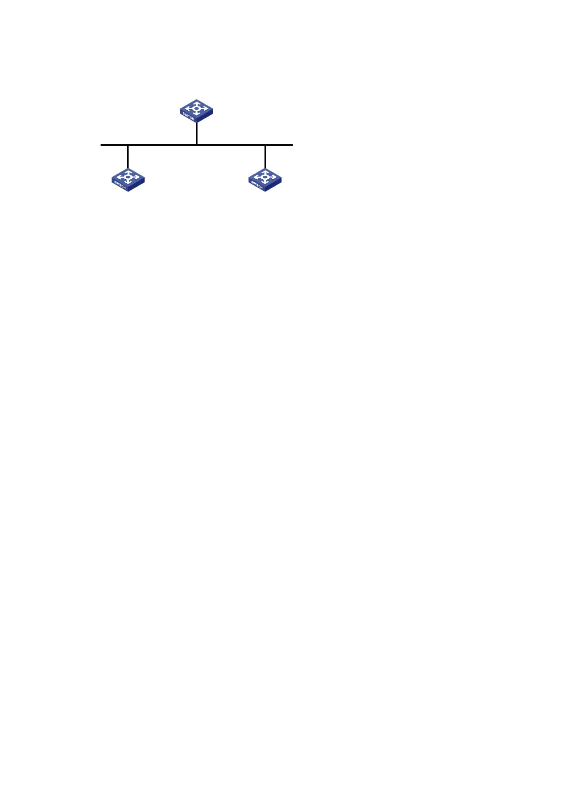
Figure 97 Network diagram
Configuration procedure
1. Configure IPv6 addresses for interfaces. (Details not shown.)
2. Configure RIPng on the switches to ensure the following: (Details not shown.)
Switch A, Switch B, and Switch C can communicate with each other at Layer 3.
Dynamic route update can be implemented among them with RIPng.
3. Enable RIPng GR on Switch A.
<SwitchA> system-view
[SwitchA] ripng 1
[SwitchA-ripng-1] graceful-restart
Verifying the configuration
# Restart RIPng process 1 on Switch A.
[SwitchA-ripng-1] return
<SwitchA> reset ripng 1 process
Reset RIPng process? [Y/N]:y
# Display GR information on Switch A.
<SwitchA> display ripng 1 graceful-restart
RIPng process: 1
Graceful Restart capability : Enabled
Current GR state : Normal
Graceful Restart period : 60 seconds
Graceful Restart remaining time: 0 seconds
RIPng NSR configuration example
Network requirements
As shown in Figure 98, Switch S, Switch A, and Switch B learn IPv6 routing information through
RIPng.
Enable RIPng NSR on Switch S to ensure correct routing when an active/standby switchover occurs
on Switch S.
Vlan-int100
2000::1/24
Vlan-int100
2000::3/24
Vlan-int100
2000::2/24
GR helper GR helper
GR restarter
Switch A
Switch CSwitch B
Router ID: 1.1.1.1
Router ID: 2.2.2.2
Router ID: 3.3.3.3
 Loading...


