43
Display RIP interface information.
display rip
process-id
interface
[
interface-type
interface-number ]
Display neighbor information for a RIP process.
display rip
process-id
neighbor
[ interface-type
interface-number ]
Display RIP NSR information.
[ process-id ]
Display routing information for a RIP process.
display rip
process-id
route
[ ip-address
{ mask-length | mask } [
verbose
] |
peer
ip-address |
statistics
]
Reset a RIP process.
reset rip
process-id
process
Clear the statistics for a RIP process.
reset rip
process-id
statistics
RIP configuration examples
Configuring basic RIP
Network requirements
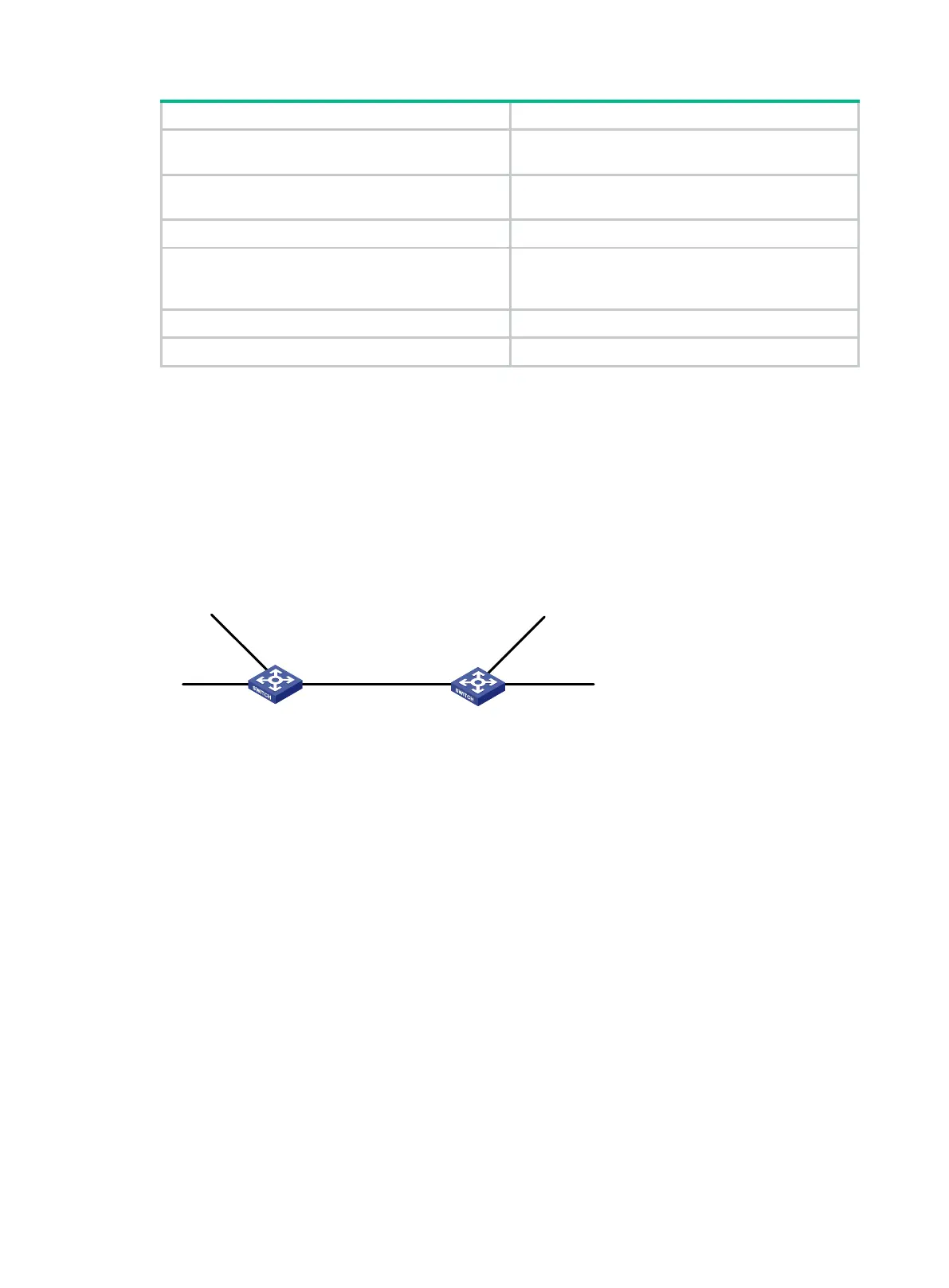
As shown in Figure 7, enable RIPv2 on all interfaces on Switch A and Switch B. Configure Switch B
to not advertise route 10.2.1.0/24 to Switch A, and to accept only route 2.1.1.0/24 from Switch A.
Figure 7 Network diagram
Configuration procedure
1. Configure IP addresses for interfaces. (Details not shown.)
2. Configure basic RIP by using either of the following methods:
(Method 1) # Enable RIP on the specified networks on Switch A.
<SwitchA> system-view
[SwitchA] rip
[SwitchA-rip-1] network 1.0.0.0
[SwitchA-rip-1] network 2.0.0.0
[SwitchA-rip-1] network 3.0.0.0
[SwitchA-rip-1] quit
(Method 2) # Enable RIP on the specified interfaces on Switch B.
<SwitchB> system-view
[SwitchB] rip
[SwitchB-rip-1] quit
[SwitchB] interface vlan-interface 100
[SwitchB-Vlan-interface100] rip 1 enable
[SwitchB-Vlan-interface100] quit
[SwitchB] interface vlan-interface 101
Vlan-int
102
2.1.1.1/24
Vlan-int100
1.1
.1.2
/24
Vlan-
int102
10.1.1.2
/24
Vlan
-int100
1.1.1.1/24
Vlan-
int101
10.2.1.1/24
Vlan-
int
101
3
.1.1
.1/
24
Switch A Switch B
 Loading...


