466
OSPFv3 GR configuration example
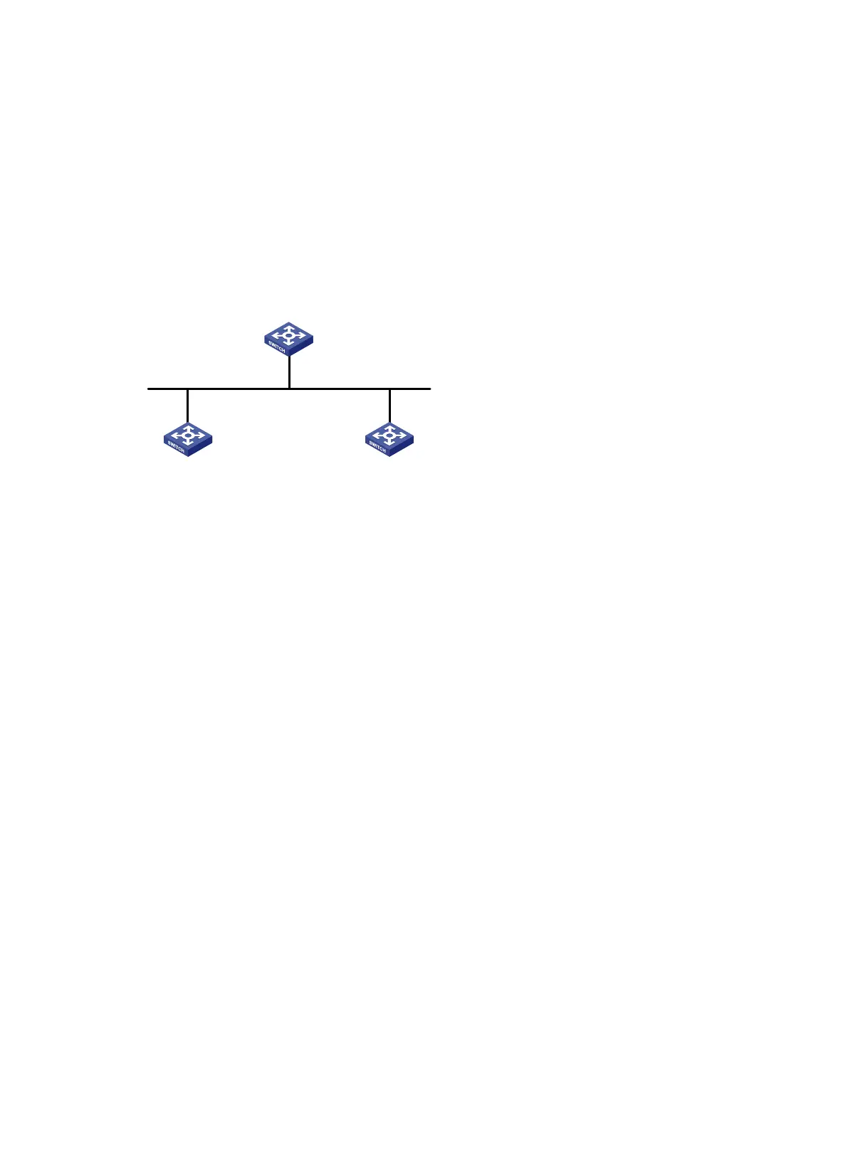
Network requirements
As shown in Figure 106:
Switch A, Switch B, and Switch C that reside in the same AS and the same OSPFv3 routing
domain are GR capable.
Switch A acts as the GR restarter. Switch B and Switch C act as the GR helpers, and
synchronize their LSDBs with Switch A through GR.
Figure 106 Network diagram
Configuration procedure
1. Configure IPv6 addresses for interfaces. (Details not shown.)
2. Configure basic OSPFv3:
# On Switch A, enable OSPFv3 process 1, enable GR, and set the router ID to 1.1.1.1.
<SwitchA> system-view
[SwitchA] ospfv3 1
[SwitchA-ospfv3-1] router-id 1.1.1.1
[SwitchA-ospfv3-1] graceful-restart enable
[SwitchA-ospfv3-1] quit
[SwitchA] interface vlan-interface 100
[SwitchA-Vlan-interface100] ospfv3 1 area 1
[SwitchA-Vlan-interface100] quit
# On Switch B, enable OSPFv3 and set the router ID to 2.2.2.2. (By default, GR helper is
enabled on Switch B.)
<SwitchB> system-view
[SwitchB] ospfv3 1
[SwitchB-ospfv3-1] router-id 2.2.2.2
[SwitchB-ospfv3-1] quit
[SwitchB] interface vlan-interface 100
[SwitchB-Vlan-interface100] ospfv3 1 area 1
[SwitchB-Vlan-interface100] quit
# On Switch C, enable OSPFv3 and set the router ID to 3.3.3.3. (By default, GR helper is
enabled on Switch C.)
<SwitchC> system-view
[SwitchC] ospfv3 1
[SwitchC-ospfv3-1] router-id 3.3.3.3
[SwitchC-ospfv3-1] quit
Vlan-
int
100
2000
::
1/
24
Vlan
-int
100
2000::
3/
24
Vlan
-
int100
2000
::2
/24
GR helper GR helper
GR restarter
Switch A
Switch CSwitch B
Router ID
: 1
.
1.
1
.1
Router ID
: 2
.2.
2.2
Router ID
:
3
.
3
.
3
.
3
 Loading...


