376
IPv6 multicast BGP configuration example
Network requirements
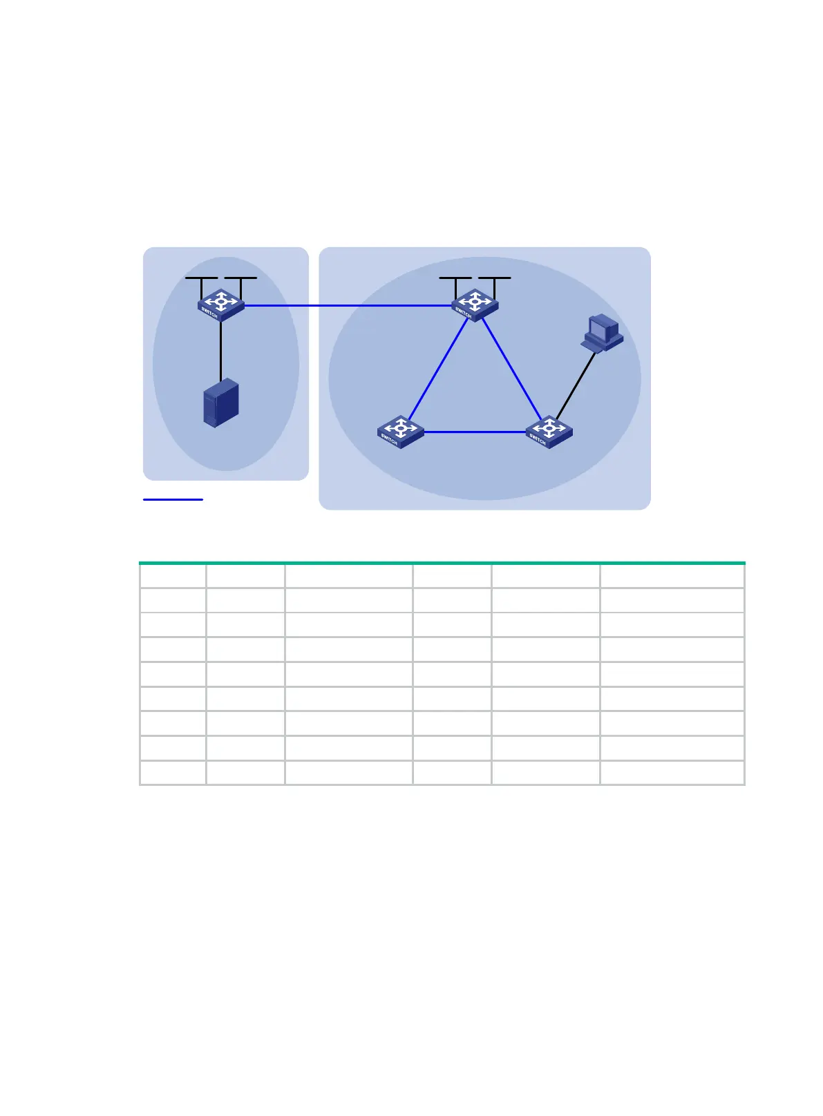
As shown in Figure 87, OSPFv3 runs within AS 100 and AS 200 to ensure intra-AS connectivity. IPv6
MBGP runs between the two ASs to exchange IPv6 unicast routes used for RPF check.
Enable Anycast RP on Switch A and Switch B.
Figure 87 Network diagram
Table 22 Interface and IP address assignment
Source - 1002::100/64 Switch B Vlan-int101 1001::2/64
Switch A Vlan-int100 1002::1/64 Vlan-int102 2001::1/64
Vlan-int101 1001::1/64 Vlan-int103 2002::1/64
Loop0 1:1::1/128 Loop0 1:1::1/128
Loop1 1:1::2/128 Loop1 2:2::2/128
Switch C Vlan-int200 3002::1/64 Switch D Vlan-int103 2002::2/64
Vlan-int102 2001::2/64 Vlan-int104 3001::2/64
Vlan-int104 3001::1/64
Configuration procedure
1. Configure IPv6 addresses for interfaces and configure OSPFv3 (this example uses OSPFv3
process 1) in AS 200 to ensure intra-AS connectivity. (Details not shown.)
2. Enable IPv6 multicast routing, IPv6 PIM-SM, and MLD, and configure BSR boundaries:
# On Switch A, enable IPv6 multicast routing globally, and enable IPv6 PIM-SM on interfaces.
<SwitchA> system-view
[SwitchA] ipv6 multicast routing
[SwitchA-mrib6] quit
[SwitchA] interface vlan-interface 100
[SwitchA-Vlan-interface100] ipv6 pim sm
[SwitchA-Vlan-interface100] quit
AS 100 AS 200
Source
Receiver
Switch A
Switch B
Switch CSwitch D
Vlan-int102
Vlan-int101 Vlan-int101
Vlan-int103
Vlan-int103
Vlan-int104
Vlan-int104
Vlan-int102
Vlan-int200
Vlan-int100
IPv6 MBGP peers
IPv6 PIM-SM 1
IPv6 PIM-SM 2
Loop1
Loop0
Loop1Loop0
 Loading...


