402
The output shows that Switch A communicates with Switch B through VLAN-interface 11.
BFD for IPv6 static routes configuration example (indirect
next hop)
Network requirements
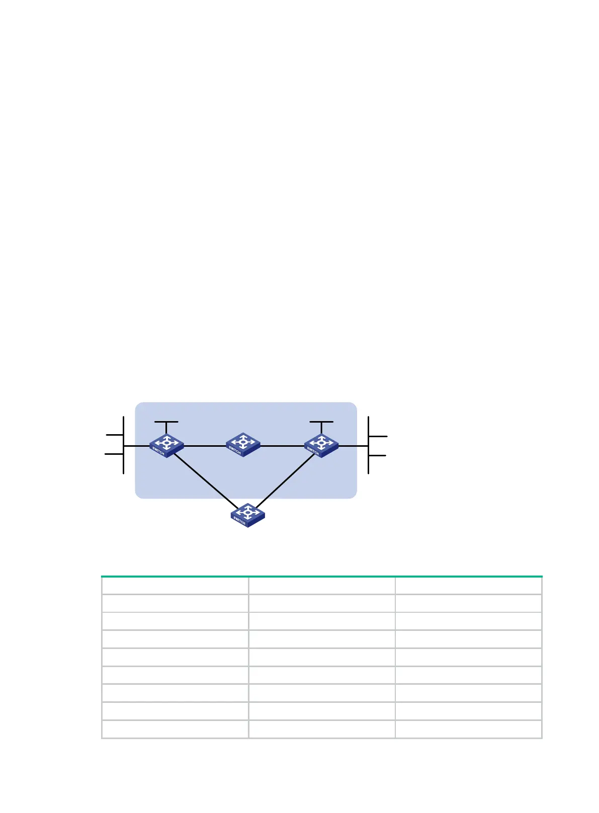
As shown in Figure 93:
Switch A has a route to interface Loopback 1 (2::9/128) on Switch B, and the output interface is
VLAN-interface 10.
Switch B has a route to interface Loopback 1 (1::9/128) on Switch A, and the output interface is
VLAN-interface 12.
Switch D has a route to 1::9/128, and the output interface is VLAN-interface 10. It also has a
route to 2::9/128, and the output interface is VLAN-interface 12.
Configure the following:
Configure an IPv6 static route to subnet 120::/64 on Switch A.
Configure an IPv6 static route to subnet 121::/64 on Switch B.
Enable BFD for both routes.
Configure an IPv6 static route to subnet 120::/64 and an IPv6 static route to subnet 121::/64 on
both Switch C and Switch D.
When the link between Switch A and Switch B through Switch D fails, BFD can detect the failure
immediately and Switch A and Switch B can communicate through Switch C.
Figure 93 Network diagram
Table 25 Interface and IP address assignment
Switch A Vlan-int10 12::1/64
Switch A Vlan-int11 10::102/64
Switch A Loop1 1::9/128
Switch B Vlan-int12 11::2/64
Switch B Vlan-int13 13::1/64
Switch B Loop1 2::9/128
Switch C Vlan-int11 10::100/64
Switch C Vlan-int13 13::2/64
Switch A Switch B
Switch C
BFD
Vlan
-int10
Vlan
-
int
11
Vlan-int
11 Vlan-int13
Vlan
-
int
13
Vlan-
int10
121::/64
120
::/64
Switch D
Vlan-int
12
Vlan-int12
Loop1
1::9
/128
Loop1
2::
9/128
 Loading...


