48
16.4.1.0/32 Direct 0 0 16.4.1.1 Vlan400
16.4.1.1/32 Direct 0 0 127.0.0.1 InLoop0
16.4.1.255/32 Direct 0 0 16.4.1.1 Vlan400
127.0.0.0/8 Direct 0 0 127.0.0.1 InLoop0
127.0.0.0/32 Direct 0 0 127.0.0.1 InLoop0
127.0.0.1/32 Direct 0 0 127.0.0.1 InLoop0
127.255.255.255/32 Direct 0 0 127.0.0.1 InLoop0
Configuring an additional metric for a RIP interface
Network requirements
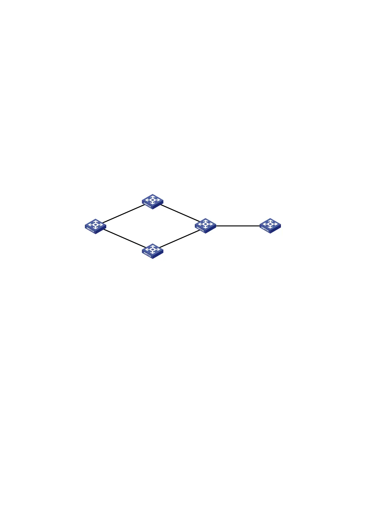
As shown in Figure 9, run RIPv2 on all the interfaces of Switch A, Switch B, Switch C, Switch D, and
Switch E.
Switch A has two links to Switch D. The link from Switch B to Switch D is more stable than that from
Switch C to Switch D. Configure an additional metric for RIP routes received from VLAN-interface
200 on Switch A so Switch A prefers route 1.1.5.0/24 learned from Switch B.
Figure 9 Network diagram
Configuration procedure
1. Configure IP addresses for interfaces. (Details not shown.)
2. Configure basic RIP:
# Configure Switch A.
<SwitchA> system-view
[SwitchA] rip 1
[SwitchA-rip-1] network 1.0.0.0
[SwitchA-rip-1] version 2
[SwitchA-rip-1] undo summary
[SwitchA-rip-1] quit
# Configure Switch B.
<SwitchB> system-view
[SwitchB] rip 1
[SwitchB-rip-1] network 1.0.0.0
[SwitchB-rip-1] version 2
[SwitchB-rip-1] undo summary
# Configure Switch C.
<SwitchC> system-view
[SwitchB] rip 1
[SwitchC-rip-1] network 1.0.0.0
[SwitchC-rip-1] version 2
Switch B
Switch C
Switch A
Switch D Switch E
Vlan-int100
1.1.1.1/24
Vlan-int100
1.1.1.2/24
Vlan-int200
1.1.2.1/24
Vlan-int200
1.1.2.2/24
Vlan-int400
1.1.3.1/24
Vlan-int300
1.1.4.1/24
Vlan-int400
1.1.3.2/24
Vlan-int300
1.1.4.2/24
Vlan-int500
1.1.5.1/24
Vlan-int500
1.1.5.2/24
 Loading...


