19
Static Routing table Status : <Inactive>
Summary Count : 0
The output shows that Switch A communicates with Switch B through VLAN-interface 11.
BFD for static routes configuration example (indirect next
hop)
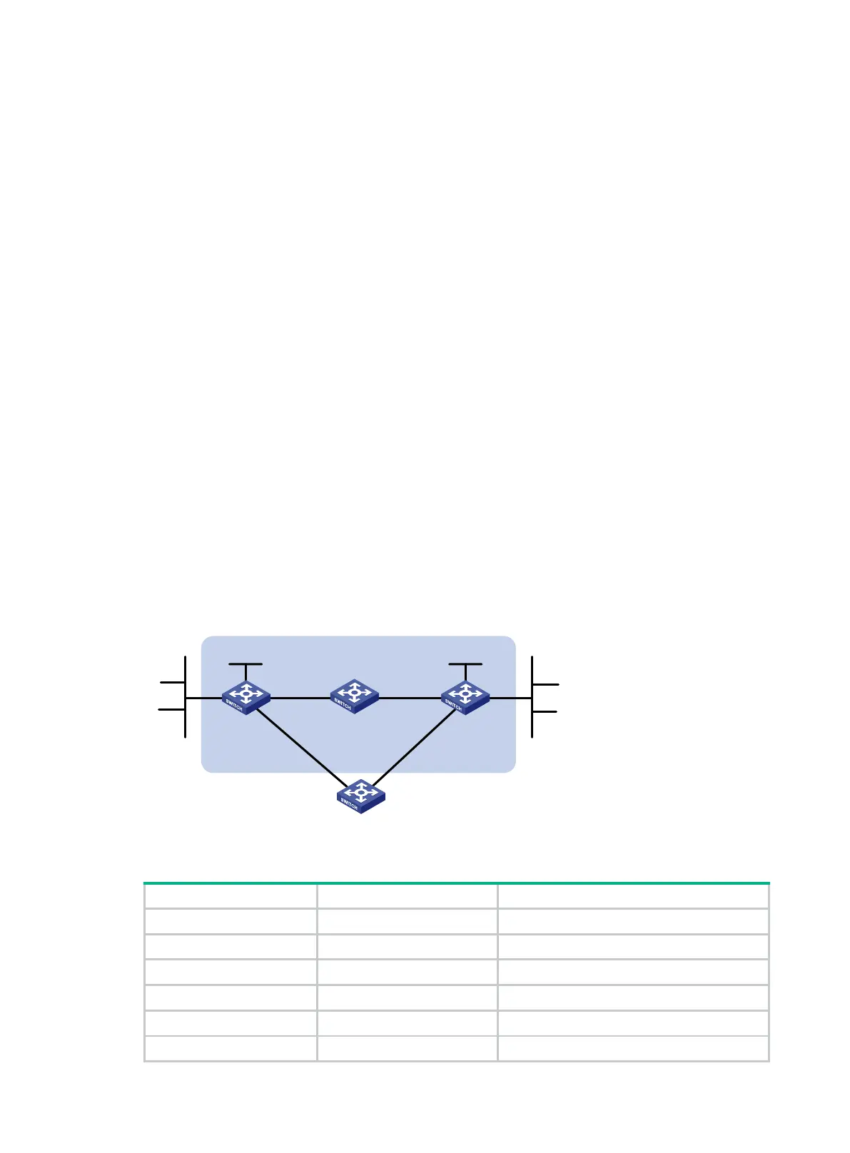
Network requirements
Figure 4 shows the network topology as follows:
Switch A has a route to interface Loopback 1 (2.2.2.9/32) on Switch B, with the output interface
VLAN-interface 10.
Switch B has a route to interface Loopback 1 (1.1.1.9/32) on Switch A, with the output interface
VLAN-interface 12.
Switch D has a route to 1.1.1.9/32, with the output interface VLAN-interface 10, and a route to
2.2.2.9/32, with the output interface VLAN-interface 12.
Configure the following:
Configure a static route to subnet 120.1.1.0/24 on Switch A.
Configure a static route to subnet 121.1.1.0/24 on Switch B.
Enable BFD for both routes.
Configure a static route to subnet 120.1.1.0/24 and a static route to subnet 121.1.1.0/24 on both
Switch C and Switch D.
When the link between Switch A and Switch B through Switch D fails, BFD can detect the failure
immediately. Switch A then communicates with Switch B through Switch C.
Figure 4 Network diagram
Table 5 Interface and IP address assignment
Switch A VLAN-interface 10 12.1.1.1/24
Switch A VLAN-interface 11 10.1.1.102/24
Switch A Loopback 1 1.1.1.9/32
Switch B VLAN-interface 12 11.1.1.1/24
Switch B VLAN-interface 13 13.1.1.1/24
Switch B Loopback 1 2.2.2.9/32
Switch A Switch B
Switch C
BFD
Vlan-int10
Vlan
-
int
11
Vlan-int11 Vlan-int13
Vlan-
int
13
Vlan-int10
121.1.1.0/24
120.1.1.0/24
Switch D
Vlan-int12
Vlan-int12
Loop1
1.1.1.9/32
Loop1
2.2.2.9/32
 Loading...


