356
Dynamic BGP peer configuration example
Network requirements
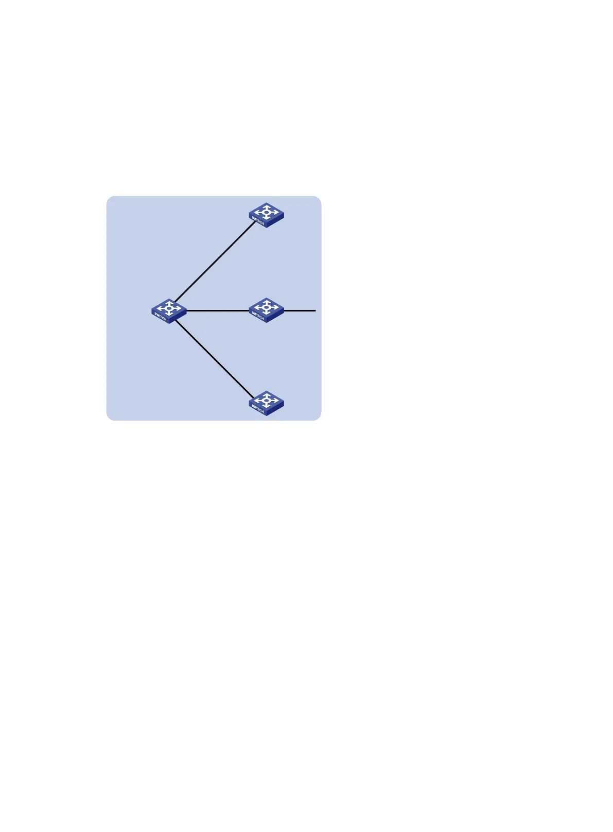
As shown in Figure 80, Switch A needs to establish IBGP peer relationships with Switch B, Switch C,
and Switch D in network 10.1.0.0/16. Configure dynamic BGP peers to simplify the configuration.
Configure Switch A as the route reflector, and configure Switch B, Switch C, and Switch D as its
clients.
Figure 80 Network diagram
Configuration procedure
1. Configure IP addresses for interfaces. (Details not shown.)
2. Configure IBGP peer relationship:
# Configure Switch A to establish dynamic BGP peer relationships with switches in network
10.1.0.0/16.
<SwitchA> system-view
[SwitchA] bgp 200
[SwitchA-bgp-default] router-id 1.1.1.1
[SwitchA-bgp-default] peer 10.1.0.0 16 as-number 200
[SwitchA-bgp-default] address-family ipv4
[SwitchA-bgp-default-ipv4] peer 10.1.0.0 16 enable
# Configure Switch B to establish an IBGP peer relationship with Switch A.
<SwitchB> system-view
[SwitchB] bgp 200
[SwitchB-bgp-default] router-id 2.2.2.2
[SwitchB-bgp-default] peer 10.1.1.1 as-number 200
[SwitchB-bgp-default] address-family ipv4
[SwitchB-bgp-default-ipv4] peer 10.1.1.1 enable
# Configure Switch C to establish an IBGP peer relationship with Switch A.
<SwitchC> system-view
[SwitchC] bgp 200
[SwitchC-bgp-default] router-id 3.3.3.3
AS 200
Vlan-int20
10.1.2
.1/24
S
2/1
Switch
A
Switch D
Switch B
Switch C
Vlan-int10
10.1.1.1/24
Vlan-int30
10.1.3.1/24
Vlan
-int20
10.1.
2.2
/24
Vlan-int30
10.1.3.2/24
Vlan
-int
10
10.
1
.1
.2
/
24
Vlan-int9
9.
1.1.
1
 Loading...


