178
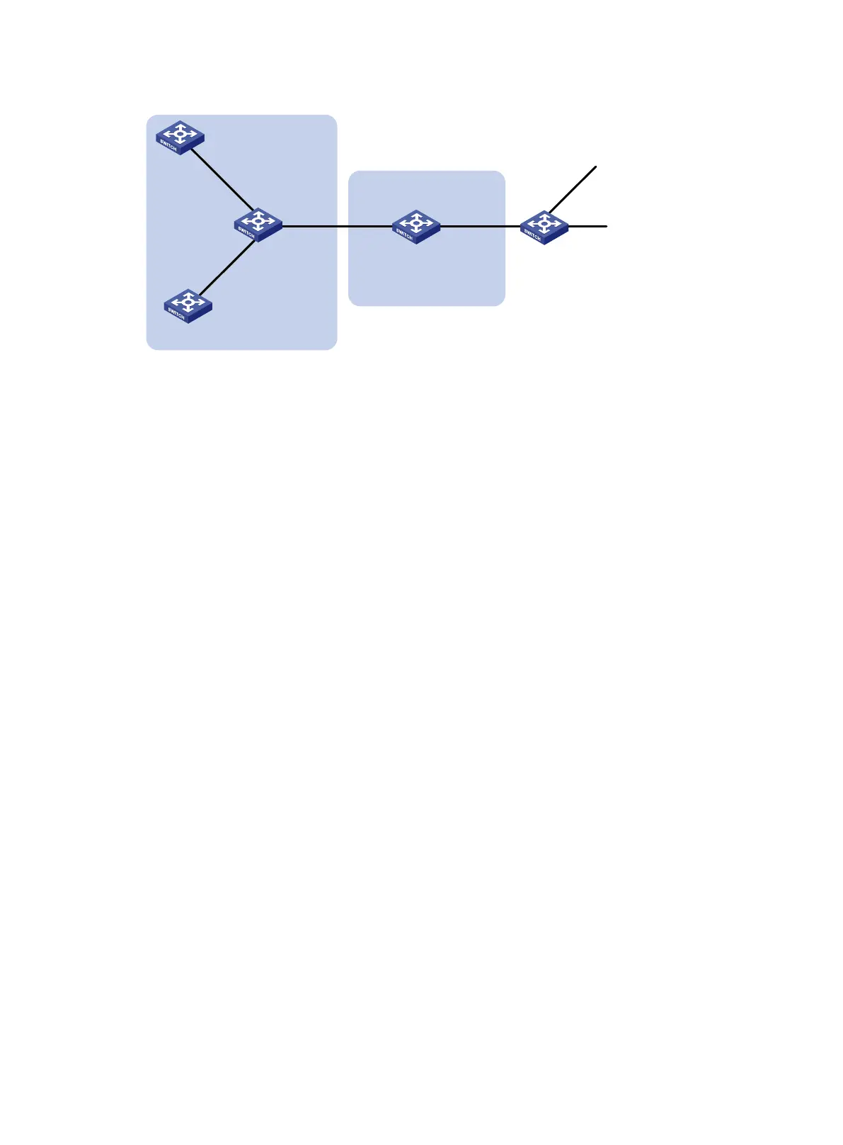
Figure 45 Network diagram
Configuration procedure
1. Configure IP addresses for interfaces. (Details not shown.)
2. Configure basic IS-IS:
# Configure Switch A.
<SwitchA> system-view
[SwitchA] isis 1
[SwitchA-isis-1] is-level level-1
[SwitchA-isis-1] network-entity 10.0000.0000.0001.00
[SwitchA-isis-1] quit
[SwitchA] interface vlan-interface 100
[SwitchA-Vlan-interface100] isis enable 1
[SwitchA-Vlan-interface100] quit
# Configure Switch B.
<SwitchB> system-view
[SwitchB] isis 1
[SwitchB-isis-1] is-level level-1
[SwitchB-isis-1] network-entity 10.0000.0000.0002.00
[SwitchB-isis-1] quit
[SwitchB] interface vlan-interface 200
[SwitchB-Vlan-interface200] isis enable 1
[SwitchB-Vlan-interface200] quit
# Configure Switch C.
<SwitchC> system-view
[SwitchC] isis 1
[SwitchC-isis-1] network-entity 10.0000.0000.0003.00
[SwitchC-isis-1] quit
[SwitchC] interface vlan-interface 200
[SwitchC-Vlan-interface200] isis enable 1
[SwitchC-Vlan-interface200] quit
[SwitchC] interface vlan-interface 100
[SwitchC-Vlan-interface100] isis enable 1
[SwitchC-Vlan-interface100] quit
[SwitchC] interface vlan-interface 300
Switch E
RIP
Vlan-int600
10.1.6.1/24
Vlan-int500
10.1.5.1/24
Vlan-int300
192.168.0.2/24
Switch D
L2
Area 20
Switch A
L1
Switch B
L1
Switch C
L1/L2
Vlan-int100
10.1.1.2/24
Vlan-int100
10.1.1.1/24
Vlan-int200
10.1.2.1/24
Vlan-int200
10.1.2.2/24
Vlan-int300
192.168.0.1/24
Area 10
Vlan-int400
10.1.4.1/24
Vlan-int400
10.1.4.2/24
 Loading...


