353
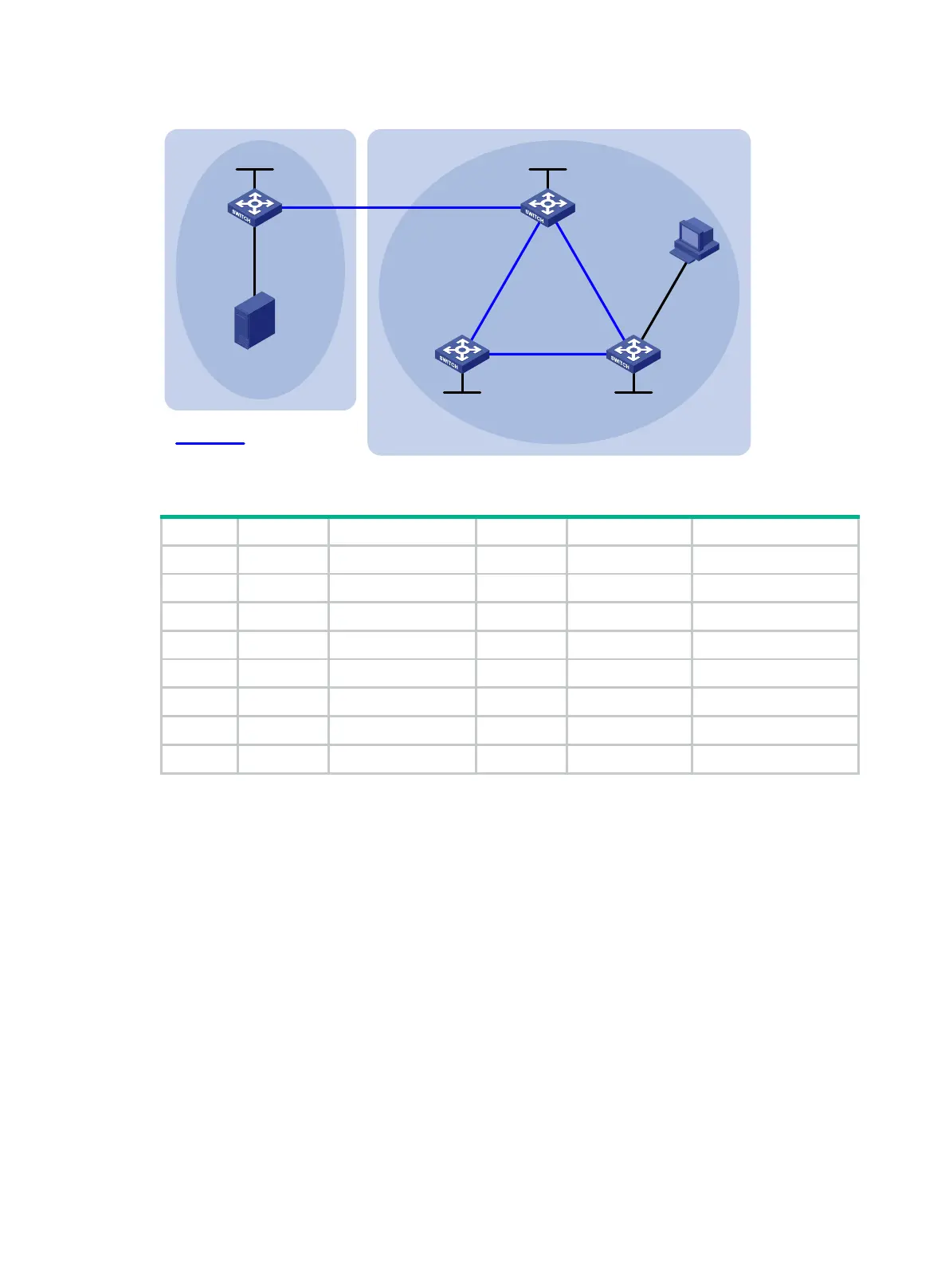
Figure 79 Network diagram
Table 20 Interface and IP address assignment
Source N/A 10.110.1.100/24 Switch C Vlan-int200 10.110.2.1/24
Switch A Vlan-int100 10.110.1.1/24 Vlan-int102 192.168.2.2/24
Vlan-int101 192.168.1.1/24 Vlan-int104 192.168.4.1/24
Loop0 1.1.1.1/32 Loop0 3.3.3.3/32
Switch B Vlan-int101 192.168.1.2/24 Switch D Vlan-int103 192.168.3.2/24
Vlan-int102 192.168.2.1/24 Vlan-int104 192.168.4.2/24
Vlan-int103 192.168.3.1/24 Loop0 4.4.4.4/32
Loop0 2.2.2.2/32
Configuration procedure
1. Configure IP addresses for interfaces and configure OSPF (this example uses OSPF process 1)
in AS 200 to ensure intra-AS connectivity. (Details not shown.)
2. Enable IP multicast routing, PIM-SM, and IGMP, and configure BSR boundaries:
# On Switch A, enable multicast routing globally, and enable PIM-SM on interfaces.
<SwitchA> system-view
[SwitchA] multicast routing
[SwitchA-mrib] quit
[SwitchA] interface vlan-interface 100
[SwitchA-Vlan-interface100] pim sm
[SwitchA-Vlan-interface100] quit
[SwitchA] interface vlan-interface 101
[SwitchA-Vlan-interface101] pim sm
[SwitchA-Vlan-interface101] quit
# Configure Switch B and Switch D in the same way that Switch A was configured.
# On Switch C, enable multicast routing globally.
<SwitchC> system-view
MBGP peers
AS 100 AS 200
Source
Receiver
Switch A
Switch B
Switch C
Switch D
Vlan-int102
Vlan-int101 Vlan-int101
Vlan-int103
Vlan-int103
Vlan-int104
Vlan-int104
Vlan-int102
Vlan-int200
Vlan-int100
PIM-SM 1
PIM-SM 2
Loop0
Loop0
Loop0
Loop0
 Loading...


