400
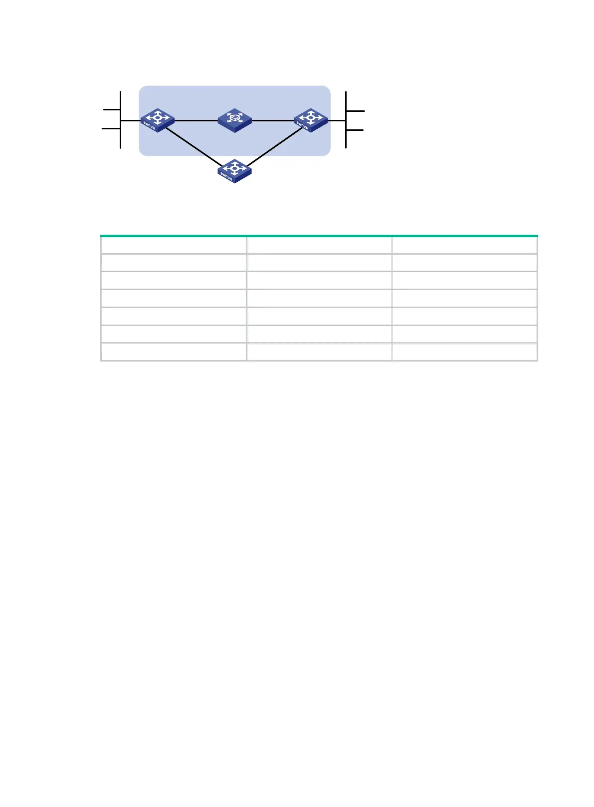
Figure 92 Network diagram
Table 24 Interface and IP address assignment
Switch A Vlan-int10 12::1/64
Switch A Vlan-int11 10::102/64
Switch B Vlan-int10 12::2/64
Switch B Vlan-int13 13::1/64
Switch C Vlan-int11 10::100/64
Switch C Vlan-int13 13::2/64
Configuration procedure
1. Configure IPv6 addresses for interfaces. (Details not shown.)
2. Configure IPv6 static routes and BFD:
# Configure IPv6 static routes on Switch A and enable BFD control mode for the static route that
traverses the Layer 2 switch.
<SwitchA> system-view
[SwitchA] interface vlan-interface 10
[SwitchA-vlan-interface10] bfd min-transmit-interval 500
[SwitchA-vlan-interface10] bfd min-receive-interval 500
[SwitchA-vlan-interface10] bfd detect-multiplier 9
[SwitchA-vlan-interface10] quit
[SwitchA] ipv6 route-static 120:: 64 vlan-interface 10 12::2 bfd control-packet
[SwitchA] ipv6 route-static 120:: 64 10::100 preference 65
[SwitchA] quit
# Configure IPv6 static routes on Switch B and enable BFD control mode for the static route that
traverses the Layer 2 switch.
<SwitchB> system-view
[SwitchB] interface vlan-interface 10
[SwitchB-vlan-interface10] bfd min-transmit-interval 500
[SwitchB-vlan-interface10] bfd min-receive-interval 500
[SwitchB-vlan-interface10] bfd detect-multiplier 9
[SwitchB-vlan-interface10] quit
[SwitchB] ipv6 route-static 121:: 64 vlan-interface 10 12::1 bfd control-packet
[SwitchB] ipv6 route-static 121:: 64 vlan-interface 13 13::2 preference 65
[SwitchB] quit
# Configure IPv6 static routes on Switch C.
Switch A Switch B
Switch C
BFD
L2 Switch
Vlan-int10
Vlan
-
int11
Vlan-int11 Vlan-int13
Vlan-int13
Vlan-int10
121::/64
120::/64
 Loading...


