425
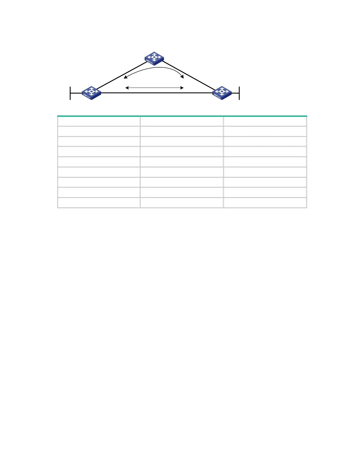
Figure 99 Network diagram
Switch A VLAN-interface 100 1::1/64
Switch A VLAN-interface 200 2::1/64
Switch A Loopback 0 10::1/128
Switch B VLAN-interface 101 3::1/64
Switch B VLAN-interface 200 2::2/64
Switch B Loopback 0 20::1/128
Switch C VLAN-interface 100 1::2/64
Switch C VLAN-interface 101 3::2/64
Configuration procedure
1. Configure IPv6 addresses for interfaces on the switches. (Details not shown.)
2. Configure RIPng on the switches to make sure Switch A, Switch B, and Switch C can
communicate with each other at Layer 3. (Details not shown.)
3. Configure RIPng FRR:
# Configure Switch A.
<SwitchA> system-view
[SwitchA] ipv6 prefix-list abc index 10 permit 20:: 128
[SwitchA] route-policy frr permit node 10
[SwitchA-route-policy-frr-10] if-match ipv6 address prefix-list abc
[SwitchA-route-policy-frr-10] apply ipv6 fast-reroute backup-interface
vlan-interface 100 backup-nexthop 1::2
[SwitchA-route-policy-frr-10] quit
[SwitchA] ripng 1
[SwitchA-ripng-1] fast-reroute route-policy frr
[SwitchA-ripng-1] quit
# Configure Switch B.
<SwitchB> system-view
[SwitchB] ipv6 prefix-list abc index 10 permit 10:: 128
[SwitchB] route-policy frr permit node 10
[SwitchB-route-policy-frr-10] if-match ipv6 address prefix-list abc
[SwitchB-route-policy-frr-10] apply ipv6 fast-reroute backup-interface
vlan-interface 101 backup-nexthop 3::2
[SwitchB-route-policy-frr-10] quit
[SwitchB] ripng 1
[SwitchB-ripng-1] fast-reroute route-policy frr
Switch A
Switch B
Switch C
Loop
0
Vlan-int100
Vlan-int
200
Vlan
-
int200
Vlan-int100
Vlan-int101
Vlan-int101
Loop0
Link A
Link B
 Loading...


