488
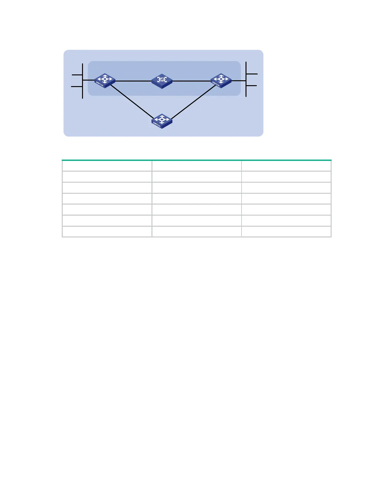
Figure 113 Network diagram
Table 28 Interface and IP address assignment
Switch A Vlan-int10 2001::1/64
Switch A Vlan-int11 2001:2::1/64
Switch B Vlan-int10 2001::2/64
Switch B Vlan-int13 2001:3::2/64
Switch C Vlan-int11 2001:2::2/64
Switch C Vlan-int13 2001:3::1/64
Configuration procedure
1. Configure IPv6 addresses for interfaces. (Details not shown.)
2. Configure IPv6 IS-IS:
# Configure Switch A.
<SwitchA> system-view
[SwitchA] isis 1
[SwitchA-isis-1] is-level level-1
[SwitchA-isis-1] network-entity 10.0000.0000.0001.00
[SwitchA-isis-1] address-family ipv6
[SwitchA-isis-1-ipv6] quit
[SwitchA-isis-1] quit
[SwitchA] interface vlan-interface 10
[SwitchA-Vlan-interface10] isis ipv6 enable 1
[SwitchA-Vlan-interface10] quit
[SwitchA] interface vlan-interface 11
[SwitchA-Vlan-interface11] isis ipv6 enable 1
[SwitchA-Vlan-interface11] quit
# Configure Switch B.
<SwitchB> system-view
[SwitchB] isis 1
[SwitchB-isis-1] is-level level-1
[SwitchB-isis-1] network-entity 10.0000.0000.0002.00
[SwitchB-isis-1] address-family ipv6
[SwitchB-isis-1-ipv6] quit
Switch A Switch B
Vlan-
int10
Vlan
-
int
10
BFD
L2
Switch
Area 0
Switch C
Vlan-
int
11
Vlan
-
int11
Vlan
-int
1
3
Vlan-
int
13
2001
:4
::/
64
2001
:
1
::/
64
 Loading...


