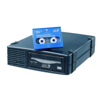
11192
Figure 4 Switch 2524 m ounting brackets
b. Adjust alignment so that the holes in the side of the mounting bracket line up with the holes in
the switch.
c. Use a #1 Phillips (cross-head) screwdriver and the four M4 scr ews (included) to attach the
mounting brackets to the switch.
2. Placetheswitchontopofnode0intherack.
3. Align the holes of the mounting brackets on both sides of the switch’s bezel with the holes in the rack.
4. On each side of the switch, insert a Phillips screw through the holes in the mounting bracket and into
the holes in the rack.
5. Tighten the Phillips screws to secur e the switch to the rack.
6. Connect the power cable to the front of the switch, run the cable through the holes in the rack to the
back of the rack but do not connect the c able to a PDU at this time.
Insta
ll the 1 Gb Ethernet switch 2824 into a rack
To install a node into the rack involves three main tasks:
• Install rails for switch 2824 in the rack
•Atta
ch rails to the 2824 switch
• Install switch 2824 in rack
Installrailsforswitch2824intherack
1. Locate the corre ct rail kit—part number 356578 –B 21.
2. Install the two slide rails to the sides of the rack.
a. Locate four of the MS screws and insert each one into a square, semi-pierced washer (included).
b. At one s ide of the rack, align the front rail holes with the holes in the back of the rack Secure by
inserting two of the provided MS screws and semi-pierced washers through the two outermost
holes in the rail and i nto the rack (see Figure 5).
28
Hardware installation
 Loading...