67
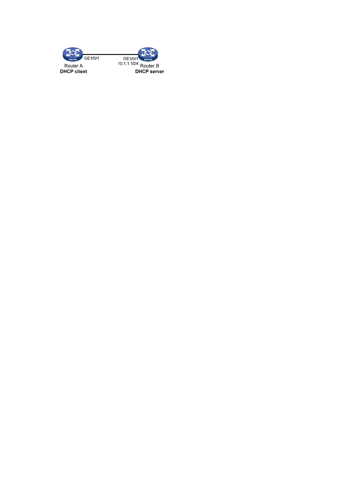
Figure 27 Network diagram
Configuration procedure
1. Specify IP addresses for the interfaces on the DHCP server. (Details not shown.)
2. Configure DHCP:
# Enable DHCP.
<RouterB> system-view
[RouterB] dhcp enable
# Enable DHCP server on interface GigabitEthernet 1/0/1.
[RouterB] interface gigabitethernet 1/0/1
[RouterB-GigabitEthernet1/0/1] dhcp select server
[RouterB-GigabitEthernet1/0/1] quit
# Create DHCP user class ss and configure a match rule to match DHCP requests in which the
hardware address is six bytes long and begins with aabb-aabb.
[RouterB] dhcp class ss
[RouterB-dhcp-class-ss] if-match rule 1 hardware-address aabb-aabb-0000 mask
ffff-ffff-0000
[RouterB-dhcp-class-ss] quit
# Create DHCP address pool aa.
[RouterB] dhcp server ip-pool aa
# Specify the subnet for dynamic allocation.
[RouterB-dhcp-pool-aa] network 10.1.1.0 mask 255.255.255.0
# Enable DHCP user class whitelist.
[RouterB-dhcp-pool-aa] verify class
# Add DHCP user class ss to the DHCP user class whitelist.
[RouterB-dhcp-pool-aa] valid class ss
[RouterB-dhcp-pool-aa] quit
Verifying the configuration
# Verify that clients matching the DHCP user class can obtain IP addresses on subnet 10.1.1.0/24
from the DHCP server. (Details not shown.)
# On the DHCP server, display the IP addresses assigned to the clients.
[RouterB] display dhcp server ip-in-use
IP address Client identifier/ Lease expiration Type
Hardware address
10.1.1.2 aabb-aabb-ab01 Jan 14 22:25:03 2015 Auto(C)
Primary and secondary subnets configuration example
Network requirements
As shown in Figure 28, the DHCP server (Router A) assigns IP addresses to DHCP clients in the
LAN.

 Loading...


