32
--- Ping statistics for 172.16.2.2 ---
5 packet(s) transmitted, 5 packet(s) received, 0.0% packet loss
round-trip min/avg/max/std-dev = 1.000/2.600/7.000/2.245 ms
# Verify the connectivity between a host on subnet 172.16.1.0/24 and a host on subnet 172.16.2.0/24.
The ping operation succeeds.
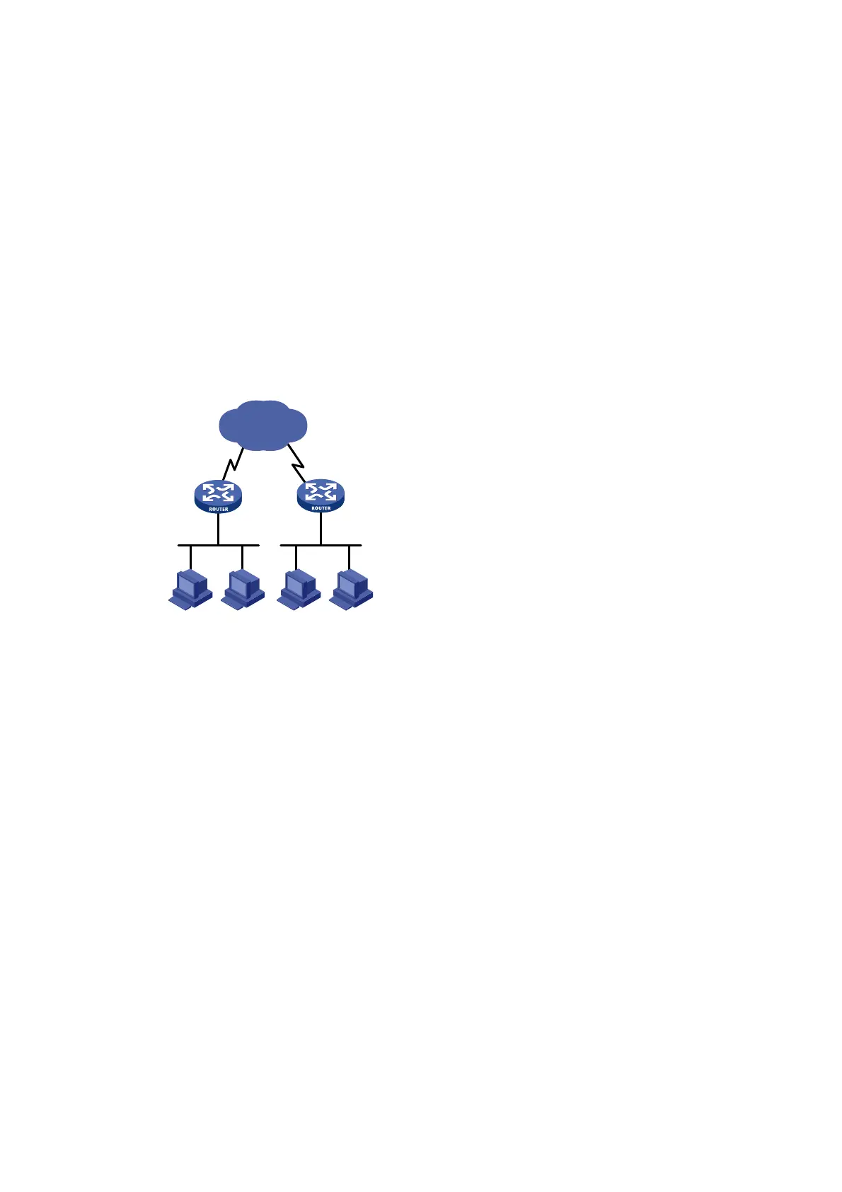
IP unnumbered configuration example
Network requirements
As shown in Figure 14, two routers on an intranet are connected to each other through serial
interfaces across a Digital Data Network. Each router connects to a LAN through an Ethernet
interface.
To save IP addresses, configure the serial interfaces to borrow IP addresses from the Ethernet
interfaces.
Figure 14 Network diagram
Configuration procedure
1. Configure Router A:
# Assign a primary IP address to GigabitEthernet 1/0/1.
<RouterA> system-view
[RouterA] interface gigabitethernet 1/0/1
[RouterA-GigabitEthernet1/0/1] ip address 172.16.10.1 255.255.255.0
[RouterA-GigabitEthernet1/0/1] quit
# Configure Serial 2/1/1 to borrow an IP address from GigabitEthernet 1/0/1.
[RouterA] interface serial 2/1/1
[RouterA-Serial2/1/1] ip address unnumbered interface gigabitethernet 1/0/1
[RouterA-Serial2/1/1] quit
# Configure a static route to the subnet attached to Router B, specifying Serial 2/1/1 as the
outgoing interface.
[RouterA] ip route-static 172.16.20.0 255.255.255.0 serial 2/1/1
2. Configure Router B:
# Assign a primary IP address to GigabitEthernet 1/0/1.
<RouterB> system-view
[RouterB] interface gigabitethernet 1/0/1
[RouterB-GigabitEthernet1/0/1] ip address 172.16.20.1 255.255.255.0
[RouterB-GigabitEthernet1/0/1] quit
Ser2/1/1
Ser2/1/1
GE1/0/1
172.16.10.1/24
GE1/0/1
172.16.20.1/24
DDN
Router BRouter A
 Loading...


