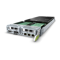
Figure 5-39 Removing a cover from a front I/O module
Step 4 Loosen the screws on the riser card. See step (1) in Figure 5-40.
Step 5 Push the latch in the arrow direction. See step (2) in Figure 5-40.
Step 6 Lift the ejector lever. See step (3) in Figure 5-40.
Step 7 Lift the riser card. See step (4) in Figure 5-40.
Figure 5-40 Removing a riser card
Step 8 Remove all PCIe cards from the riser card, and place the riser card in an ESD bag.
For details about how to remove a PCIe card, see 5.5.7 Removing a PCIe Card.
----End
RH8100 V3 Server
User Guide 5 Removing and Installing Parts of the RH8100 V3
Issue 30 (2019-12-19) Copyright © Huawei Technologies Co., Ltd. 157
 Loading...
