Do System Tests to Identify Defective Components
Powermax65/85/105 SYNC Troubleshooting Guide 810430 107
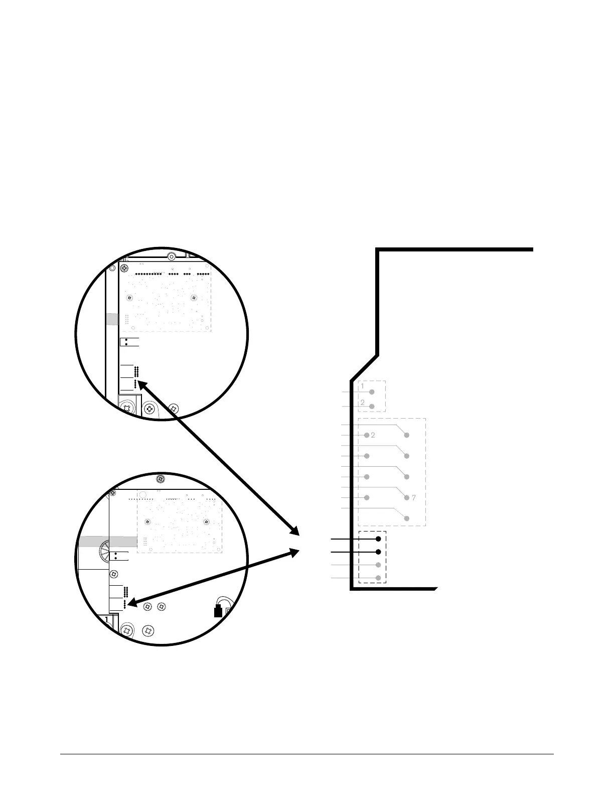
4. At J21or J18 on the power PCB, do a check for continuity on pin 1 (red) and pin 2 (black). Refer
to Figure 25. Is there continuity on both pins?
If yes, there is possibly a problem with the wiring harness for the machine interface
receptacle. Replace the machine interface receptacle with voltage divider PCB assembly
(228697 for Powermax65/85 SYNC; 528045 for Powermax105 SYNC).
If no, there is possibly a problem with the power PCB. Replace the power PCB.*
* The problem will more often be with the power PCB. In unusual situations, there can be a problem with the
DSP PCB. If possible, install a different DSP PCB that is known to operate correctly before you replace the
power PCB to see if the problem goes away.
Figure 25 – Machine interface pins for plasma start on the power PCB
12
15
11
20
17
OR
VI
GR
GR
6
1
RED
J21
ORG
J20
J12
B
R
J4 J2 J1J3
J6 J5 J2 J1
J22
RED
J18
ORG
J17
J11
B
R
Powermax65/85 SYNC
Powermax105 SYNC