Prepare to Troubleshoot Internal Components
Powermax65/85/105 SYNC Troubleshooting Guide 810430 31
Table 4 — Powermax105 SYNC power switch resistance values
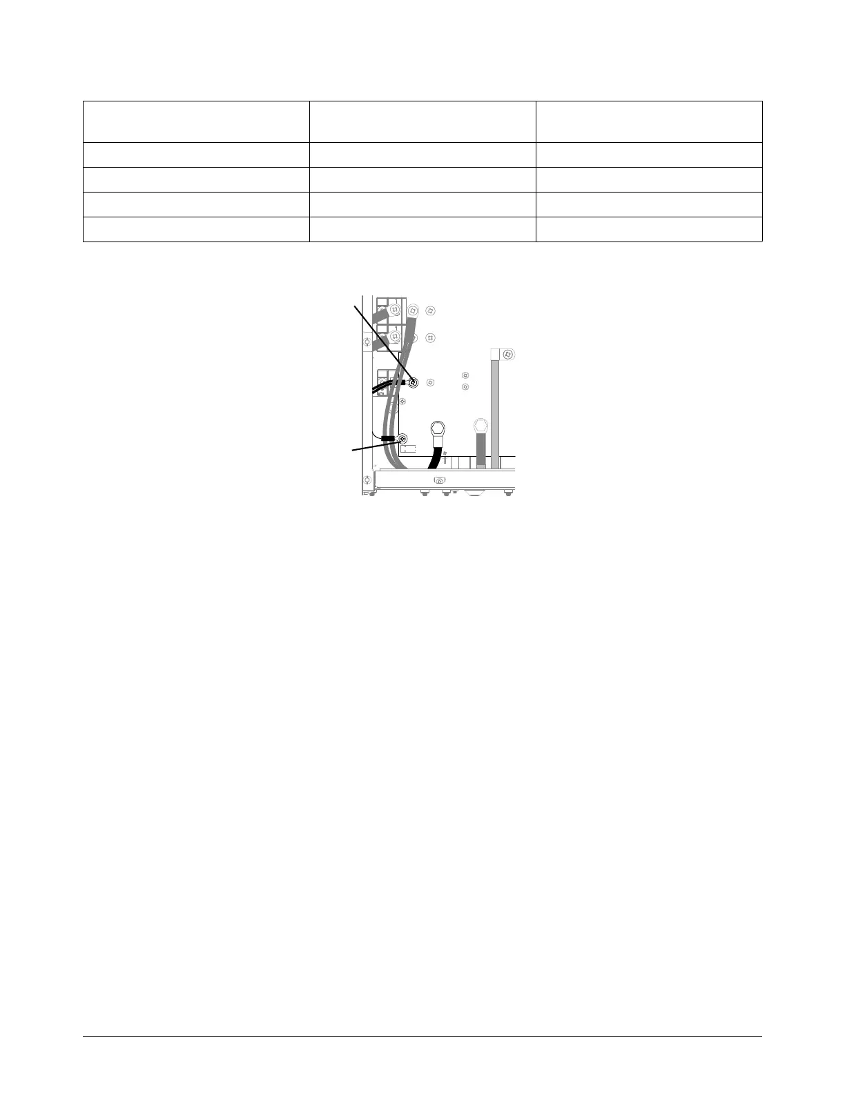
Figure 3 —Powermax105SYNC
8. If you do not find a problem during the internal inspection or the initial resistance check, and the
power supply still does not operate correctly, do the following:
Refer to Troubleshooting for Common Problems on page 63. This section gives the causes
and solutions for many common troubleshooting conditions.
Refer to the system wiring diagrams on page 173.
Make sure that you understand the theory of operation before you do troubleshooting
procedures. Refer to Theory of operation on page 169.
Before you purchase a major replacement component, make sure that you correctly identify
the problem and solution with Hypertherm Technical Service or the nearest Hypertherm
repair facility.
Measure resistance from Power PCB location
All models with torch
disconnected
Work lead to nozzle J27 to black wire 230 k
Work lead to electrode J27 to J28 (red wire) 9 k
Electrode to nozzle J28 (red wire) to black wire 230 k
Output to ground > 20 m