Prepare to Troubleshoot Internal Components
30 810430 Troubleshooting Guide Powermax65/85/105 SYNC
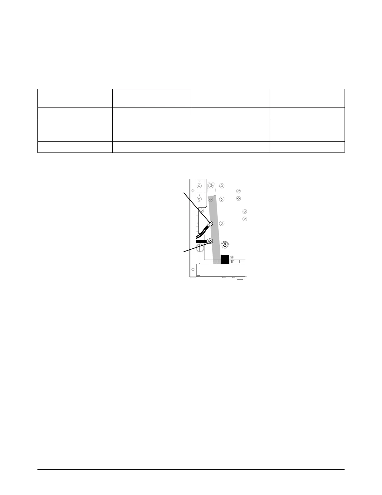
7. Measure the output resistance for the values shown in the following tables and figures:
Powermax65/85 SYNC: Refer to Table 3 and Figure 2 on page 30.
Powermax105 SYNC: Refer to Table 4 and Figure 3 on page 31.
Table 3 — Powermax65/85 SYNC power switch resistance values
Figure 2 — Powermax65/85 SYNC
Measure resistance from CSA power PCB location
CE/CCC power PCB
location
Approximate values with
torch disconnected
Work lead to nozzle J26 to black wire J27 to black wire 230 k
Work lead to electrode J26 to J28 (red wire) J27 to J29 (red wire) 15 k
Electrode to nozzle J28 (red wire) to black wire J29 (red wire) to black wire 230 k
Output to ground > 20 M
WORK
LEAD
J26 (J27)
J28 (J29)