Troubleshooting for Fault Codes
Powermax65/85/105 SYNC Troubleshooting Guide 810430 59
3-nn-n fault codes
Fault
code
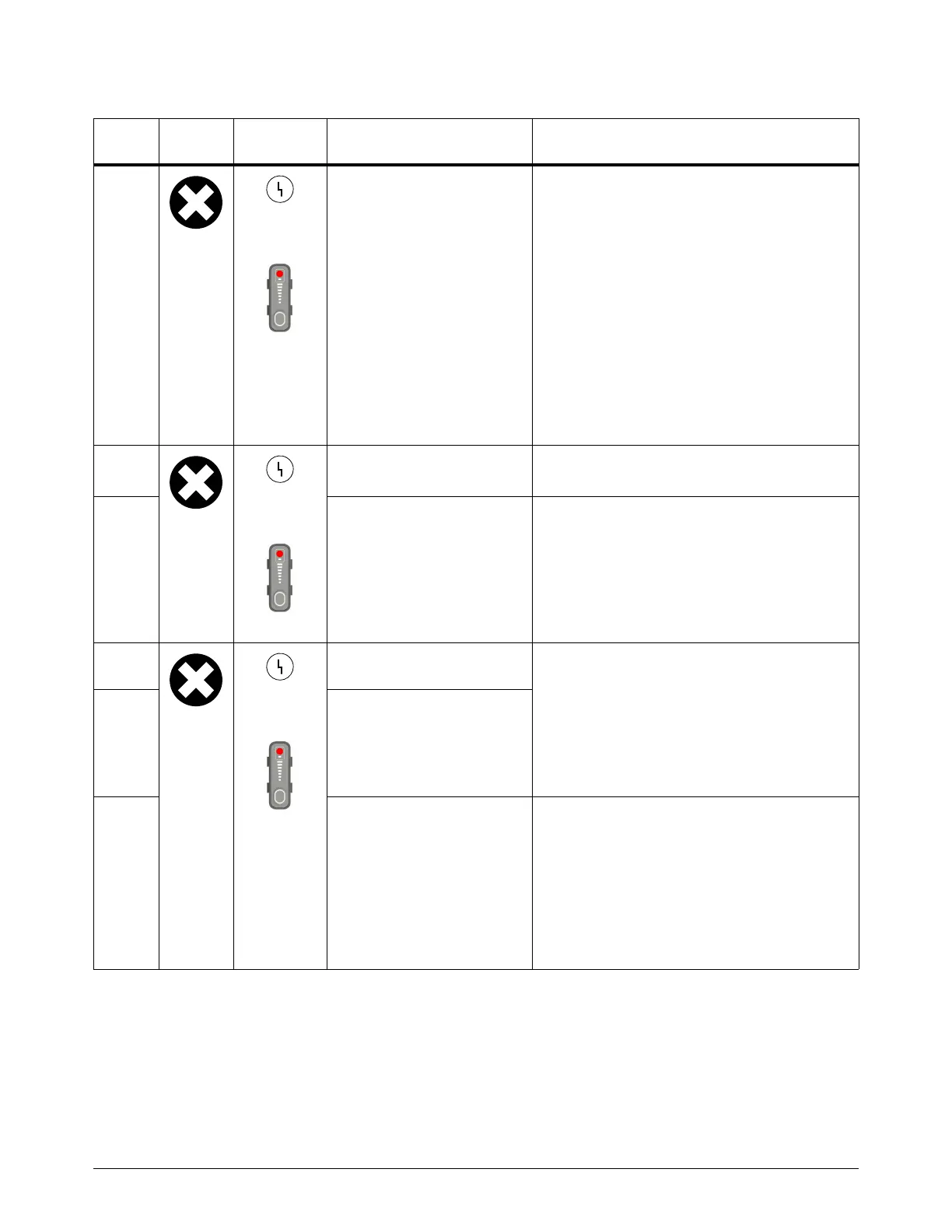
Fault
icon
Fault
LEDs Description Solutions
3-00-0
Yellow
Red
The DC bus voltage (VBUS)
is out of range.
• Examine the circuitry for the PFC IGBT
(CSA and Powermax105 SYNC CE/CCC
230V– 400V models only).
• Use an IGBT tester to do a test of the PFC
IGBT (CSA and Powermax105 SYNC
CE/CCC 230 V – 400 V models only).
• Measure the bus voltage from Test
Point (TP) W (-) to TP R (+) on the power
PCB. Refer to Test 2 – DC power bus on
page 83. Does the voltage match the bus
voltage value in the VB field on the POWER
SUPPLY DATA screen? If not, replace the
DSP PCB. Refer to Test 5 – Flyback circuit
(DC minor voltages) on page 94.
3-10-0
Yellow
Red
The fan speed is less than the
minimum speed.
• Clean the fan assembly.
•Do Test 11 – Fan on page 120.
3-10-1 A fan fault occurred. • Examine the related wiring.
•Do Test 11 – Fan on page 120.
• If necessary, replace the fan.
3-11-0
Yellow
Red
The PFC IGBT temperature
sensor is open.
This is applicable to CSA and
Powermax105 SYNC CE/CCC 230 V – 400 V
models only.
• Examine the related wiring.
•Do Test 4 – Inverter thermal sensor and
PFC temperature sensor on page 91.
• If necessary, replace the PFC IGBT.
3-11-1 The PFC IGBT temperature
sensor short-circuited.
3-11-2 There is a PFC IGBT
temperature sensor circuit
fault.
This is applicable to CSA and
CE/CCC 230 V – 400 V models only.
• Examine the temperature circuit on the
power PCB.
•Do Test 4 – Inverter thermal sensor and
PFC temperature sensor on page 91.
• If Test 4 does not identify the problem,
replace the power PCB.