Troubleshooting for Fault Codes
60 810430 Troubleshooting Guide Powermax65/85/105 SYNC
3-20-0
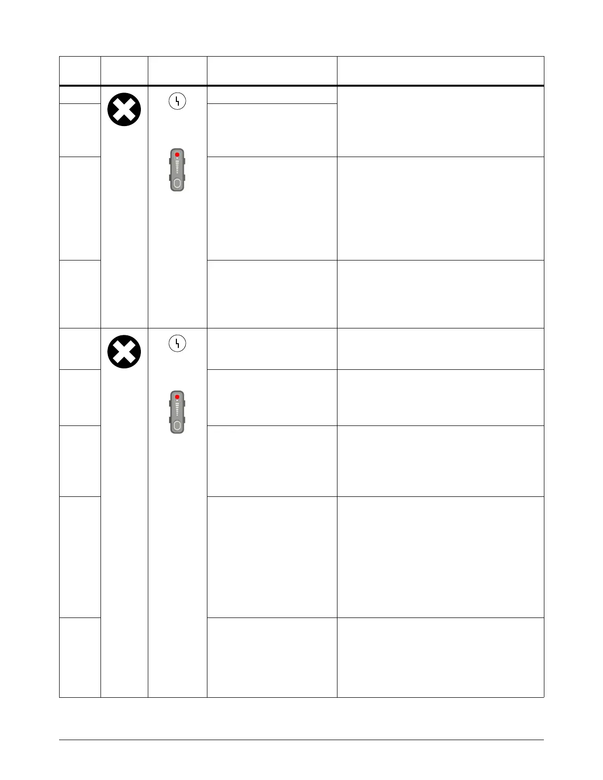
Yellow
Red
The fill valve is not connected. • Examine the related wiring.
•Do Test 9 – Solenoid valve electronic
regulator on page 112.
• If necessary, replace the solenoid valve
assembly.
3-20-1 The dump valve is not
connected.
3-20-2 The plasma power supply
does not recognize the
solenoid valve electronic
regulator.
• The DSP PCB does not recognize the
solenoid valve electronic regulator.
• Make sure that the jumper at J4
(Powermax65/85 SYNC CSA models) or
J6 (all other models) on the power PCB is in
the correct position. Refer to the wiring
diagram for your system, starting on
page 173.
3-20-3 The solenoid valve electronic
regulator is not receiving
power.
• Carefully examine the 10-pin connector at
J4 (Powermax65/85 SYNC CSA models)
or J6 (all other models) on the power PCB.
• If necessary, replace the solenoid valve
assembly.
3-41-0
Yellow
Red
A driver integrated circuit (IC)
fault occurred.
• A signal fault occurred in the Start/Transfer
relay or the soft-start (inrush current) relay
on the power PCB.
3-42-0 The 5 VDC or 24 VDC
supply is out of range.
• The 5 VDC or 24 VDC supply from the
flyback circuit is out of range.
•Do Test 5 – Flyback circuit (DC minor
voltages) on page 94.
3-42-1 The 18 VDC supply is out of
range.
The 18 VDC supply from the flyback circuit is
out of range.
• Replace the power PCB.
• Examine the inverter IGBT, and replace it if
necessary.
3-43-0 The inverter capacitors are
not balanced.
The inverter capacitors are not balanced when
the voltage across one or both of the capacitors
is more than 25% different than nominal.
• Make sure that the bus voltage is correct for
each capacitor in your system. Do Test 2 –
DC power bus on page 83.
• Do a test of the inverter IGBT. Refer to
Hypertherm IGBT tester on page 32.
• Replace the bulk capacitors.
3-44-1 The PFC IGBT current is too
high.
This is applicable to CSA and
to Powermax105 SYNC
230 V – 400 V CE models
only.
The current in the PFC IGBT is too high.
• Do a test of the PFC IGBT. Refer to
Hypertherm IGBT tester on page 32.
• Replace the PFC IGBT if it is defective.
• If necessary, replace the power PCB.
Fault
code
Fault
icon
Fault
LEDs Description Solutions