Troubleshooting for Fault Codes
Powermax65/85/105 SYNC Troubleshooting Guide 810430 61
3-51-1
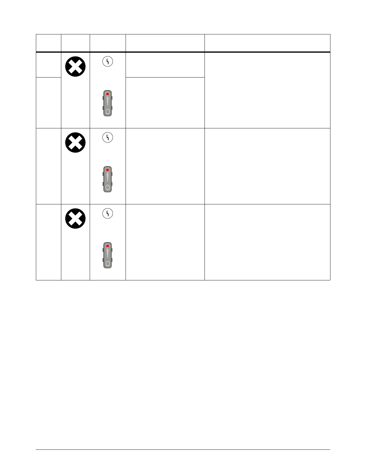
Yellow
Red
An inverter IGBT saturation
fault occurred. The inverter
current is too high.
The top and bottom inverter IGBTs are starting
in phase instead of 180° out of phase.
• Do a test of the 2 inverter IGBTs. Refer to
Hypertherm IGBT tester on page 32.
•Do Test 3 – Output diodes on page 90.
• Replace the module if either IGBT is
defective.
• If necessary, replace the power PCB.
3-52-0 A short circuit caused
high-current distortion in the
inverter IGBT. This is
sometimes referred to as a
shoot-through.
3-60-0
Yellow
Red
The DSP PCB does not
recognize the power PCB.
• Make sure that the correct power PCB is
installed for the plasma power supply.
3-70-0
Yellow
Red
There is an internal serial
communications fault
between the DSP PCB and
power PCB.
There is a fault with the communication between
the DSP PCB and the power PCB.
• Examine the cable that connects to both the
DSP PCB and the power PCB.
• If necessary, replace the DSP PCB or the
power PCB.
Fault
code
Fault
icon
Fault
LEDs Description Solutions