Do System Tests to Identify Defective Components
84 810430 Troubleshooting Guide Powermax65/85/105 SYNC
5. Measure the voltage of the inverter IGBT . For the correct voltages for your system, refer to
Figure 12 on page 85 and Figure 13 on page 86.
All values are ±15%.
6. Measure the voltage between the bulk capacitors before you fire the torch.
7. Measure the voltage between the bulk capacitors while you fire the torch.
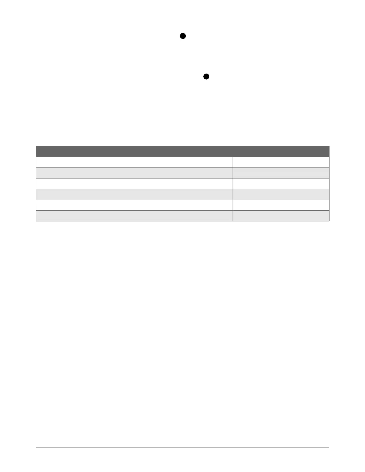
8. The voltage between the bulk capacitors must be approximately the same before and during
torch operation. The voltage must also be approximately half of the bus voltage, as shown in
Table 6.
Table 6
9. If the voltage measurements are out of range, replace the power PCB.
Powermax system and input power Correct voltage (approximate)
Powermax65/85/105 SYNC CSA on 200 VAC – 480 VAC input power 375 VDC
Powermax65/85/105 SYNC CSA on 600 VAC input power 425 VDC
Powermax65/85 SYNC CE/CCC 280 VDC
Powermax105 SYNC 230 V – 400 V CE 375 VDC
Powermax105SYNC 380V CCC 265VDC
Powermax105 SYNC 400 V CE 280 VDC