8.6 How to replace components
8-20
8. Maintenance and Inspection
2) Loosen the screws (2 pcs) at the bottom of the motor cover assembly and take off
the cover at the bottom.
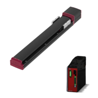
3) Take off the connectors on Motor Cable [B], Encoder Cable [C] and Brake Cable [D]
for the brake-equipped type, loosen the screws (2 pcs) at the top of the motor cover
assembly, and take off the old motor cover assembly (top).
4) Put on a new motor cover assembly (top), and put on the connectors on Motor Cable
[B], Encoder Cable [C] and Brake Cable [D] for the brake-equipped type.
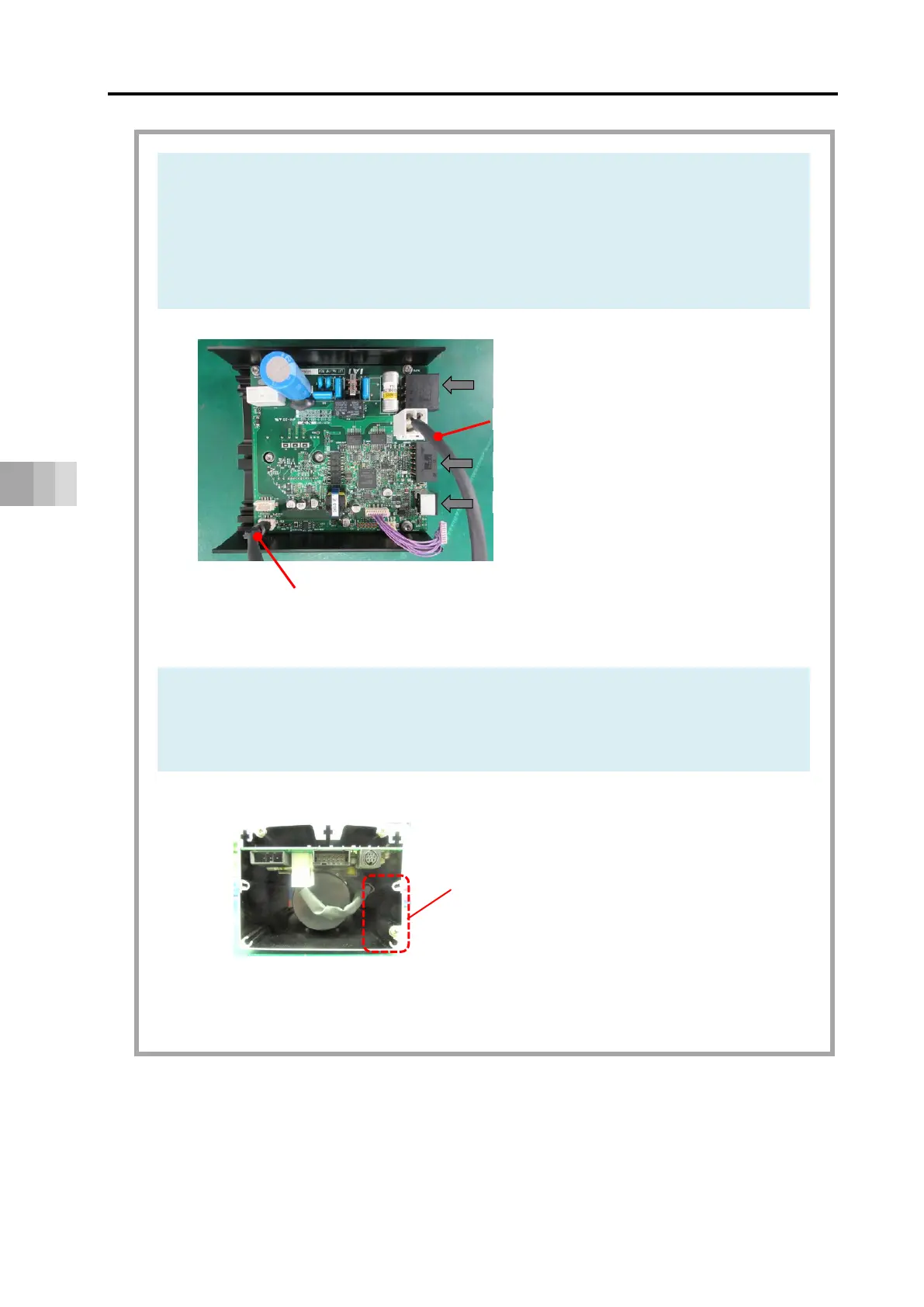
Store cables to the space at the right bottom in the view from the end cover side.
Storage of Cables
Power I/O connector
Encoder cable [C]
(Ferrite core on PCB side)
Motor cable [B]
Teaching port
Motor power supply connector
Cable Storage Space
The space at the right bottom in
the view from end cover side.
 Loading...