ecification
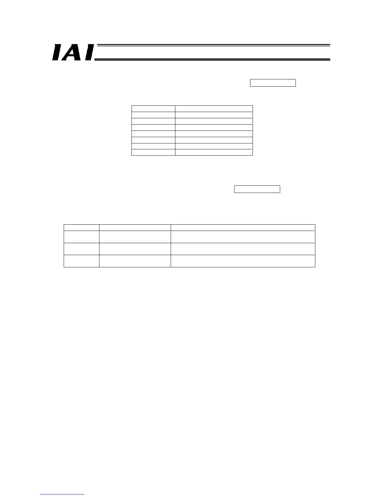
(22) Current Position Number Signal (PE0 to PE6) [Solenoid valve mode 1] PLC Input Signal
Position numbers (0 to 6) that received move command is output individually when positioning is completed.
Table for Output Signal and Completed Position
Output signal Completed position
PE0 Position No.0
PE1 Position No.1
PE2 Position No.2
PE3 Position No.3
PE4 Position No.4
PE5 Position No.5
PE6 Position No.6
(Note) It turns OFF when servo is OFF or at an emergency stop. When servo turns ON again, and if the actuator is
within the positioning band, it will turn ON again, however, if it is not within the band, it will remain OFF.
(23) Position Detection Output (LS0 to LS2) [Solenoid valve mode 2] PLC Input Signal
It has the same meaning as the LS signal of the air cylinder. It turns ON when the current position is within the
positioning band of each target position.
(Note) Even if the servo turns OFF or an emergency stop is occurred when the actuator is stopped at the target position,
it remains ON as long as it is within the positioning band.
Input signal Position detection Remarks
LS0 Rear end position
The detected position is defined in the “Position” and
“Positioning Band” fields for position No. 0.
LS1 Front end position
The detected position is defined in the “Position” and
“Positioning Band” fields for position No. 0.
LS2 Intermediate point position
The detected position is defined in the “Position” and
“Positioning Band” fields for position No. 0.

 Loading...


