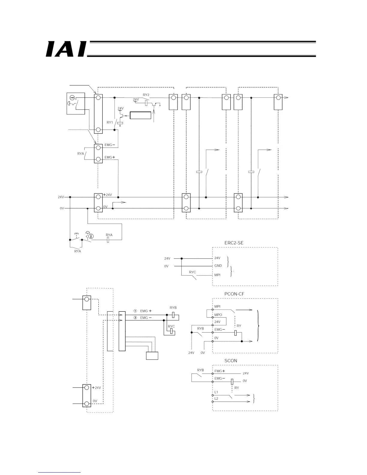
(2) An emergency stop circuit for normal layout when external SIO link is used is shown below.
[1]
[3]
[1]
[2]
[3]
EMG connector
TP connector
Teaching pendant
GateWayR unit Axis controller unit
ROBONET Communication Connector
Drive-source cutoff signal
(CPU control signal)
Motor drive source
Drive-source cutoff relay
Power-supply input terminal block
Internal power supply common
GND
Emergency
stop reset
Emergency stop
TP connection
detection circuit
Axis controller unit
Motor drive source
Drive-source cutoff relay
red
black

 Loading...


