ecification
(3) PROFIBUS (RGW-PR)
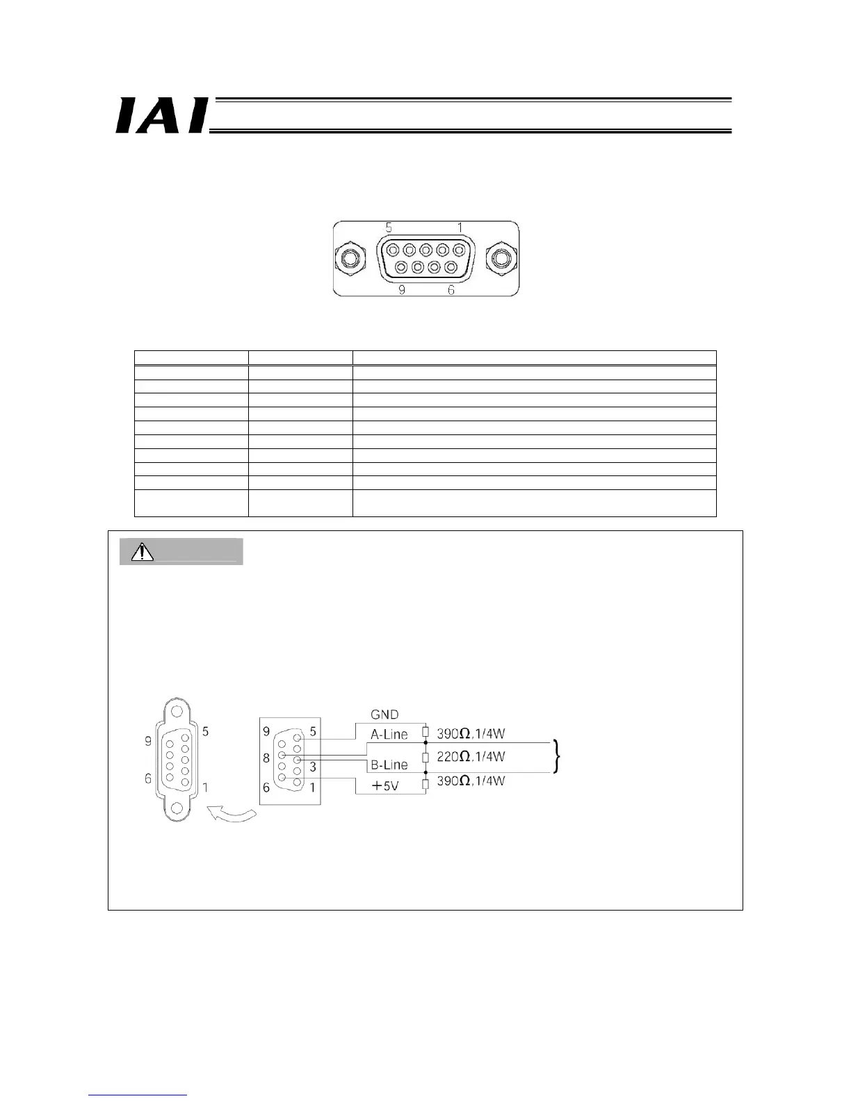
RGW-PR connector: D-Sub, 9-pin connector (female)
PROFIBUS communication connector
Pin number Signal name Explanation
1 NC Not connected
2 NC Not connected
3 B-Line Communication line B (RS485)
4 RTS Send request
5 GND Signal ground (insulated)
6 +5 V +5-V output (insulated)
7 NC Not connected
8 A-Line Communication line A (RS485)
9 NC Not connected
Housing
Shield Cable shield
This signal is connected to the enclosure.
Caution
(1) The mating (cable-end) connector (D-sub, 9-pin connector) is not supplied.
(2) The RGW-PR does not have terminal resistor setting switches. If the RGW-PR is connected at the end of a network,
connect a terminal resistor to the network connector or use a connector with terminal resistor, as specified below.
z Connecting a terminal resistor
z PROFIBUS connector (with terminal resistor)
(Example) SUBCON-PLUS-PROFIB/AX/SC (Phoenix Contact)
For details, refer to the operation manual of the master unit.
Female connector
on RGW-PR end
Male connector on network
end (view from the side
opposite the insertion side)
Network wiring

 Loading...


