ecification
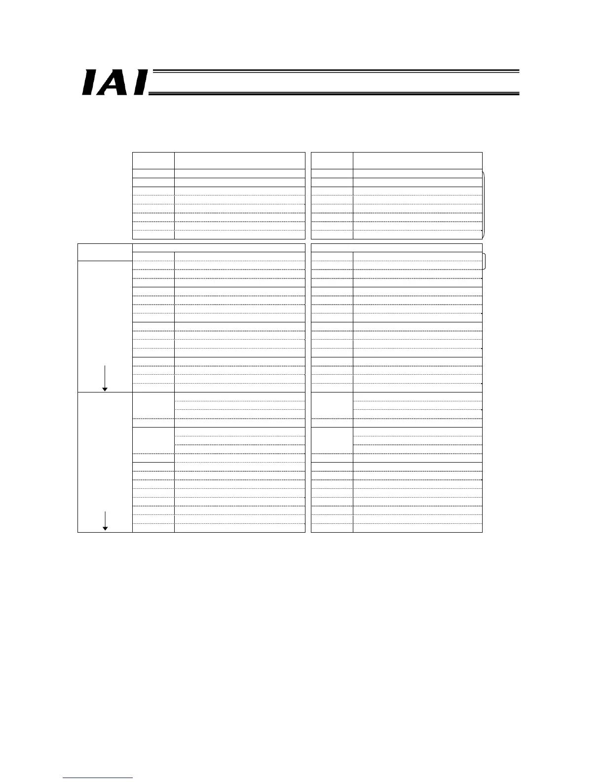
Example of Overall CC-Link Address Configuration (Positioner 2 mode and Solenoid valve mode)
An example of connecting 16 axes operating in the positioner 2 mode, Solenoid valve mode 1 or 2 is shown.
PLC output ⇒ ROBONET ROBONET⇒ PLC input
Output
register
Upper byte Lower byte
Input
register
Upper byte Lower byte
RY0F to 00 Gateway control signal 0 RX0F to 00 Gateway status signal 0
RY1F to 10 Gateway control signal 1 RX1F to 10 Gateway status signal 1
RY2F to 20 Request command RX2F to 20 Response command
RY3F to 30 Data 0 RX3F to 30 Data 0
RY4F to 40 Data 1 RX4F to 40 Data 1
RY5F to 50 Data 2 RX5F to 50 Data 2
RY6F to 60 Data 3 RX6F to 60 Data 3
RY7F to 70 (Cannot be used) RX7F to 70 (Cannot be used)
8-word
fixed area
*1
Output register Input register
PLC master expanded
cyclic setting
RWw 00H
(Axis 0) Command position number
RWr 00H
(Axis 0) Completed position number
RWw 01H
(Axis 0) Control signal
RWr 01H
(Axis 0) Status signal
RWw 02H (Axis 1) Command position number RWr 02H (Axis 1) Completed position number
RWw 03H
(Axis 1) Control signal
RWr 03H
(Axis 1) Status signal
2 words
RWw 04H
(Axis 2) Command position number
RWr 04H
(Axis 2) Completed position number
RWw 05H
(Axis 2) Control signal
RWr 05H
(Axis 2) Status signal
RWw 06H
(Axis 3) Command position number
RWr 06H
(Axis 3) Completed position number
RWw 07H
(Axis 3) Control signal
RWr 07H
(Axis 3) Status signal
RWw 08H
(Axis 4) Command position number
RWr 08H
(Axis 4) Completed position number
RWw 09H
(Axis 4) Control signal
RWr 09H
(Axis 4) Status signal
RWw 0AH
(Axis 5) Command position number
RWr 0AH
(Axis 5) Completed position number
RWw 0BH
(Axis 5) Control signal
RWr 0BH
(Axis 5) Status signal
RWw 0CH
(Axis 6) Command position number
RWr 0CH
(Axis 6) Completed position number
RWw 0DH
(Axis 6) Control signal
RWr 0DH
(Axis 6) Status signal
RWw 0EH
(Axis 7) Command position number
RWr 0EH
(Axis 7) Completed position number
16 words
x1 setting,
4 stations
*2
RWw 0FH
(Axis 7) Control signal
RWr 0FH
(Axis 7) Status signal
RWw 10H (Axis 8) Command position number
RWr 10H
(Axis 8) Completed position number
RWw 11H (Axis 8) Control signal
RWr 11H
(Axis 8) Status signal
RWw 12H (Axis 9) Command position number
RWr 12H
(Axis 9) Completed position number
RWw 13H (Axis 9) Control signal
RWr 13H
(Axis 9) Status signal
RWw 14H (Axis 10) Command position number
RWr 14H
(Axis 10) Completed position number
RWw 15H (Axis 10) Control signal
RWr 15H
(Axis 10) Status signal
RWw 16H (Axis 11) Command position number
RWr 16H
(Axis 11) Completed position number
RWw 17H (Axis 11) Control signal
RWr 17H
(Axis 11) Status signal
RWw 18H (Axis 12) Command position number
RWr 18H
(Axis 12) Completed position number
RWw 19H (Axis 12) Control signal
RWr 19H
(Axis 12) Status signal
RWw 1AH (Axis 13) Command position number
RWr 1AH
(Axis 13) Completed position number
RWw 1BH (Axis 13) Control signal
RWr 1BH
(Axis 13) Status signal
RWw 1CH (Axis 14) Command position number
RWr 1CH
(Axis 14) Completed position number
RWw 1DH (Axis 14) Control signal
RWr 1DH
(Axis 14) Status signal
RWw 1EH (Axis 15) Command position number
RWr 1EH
(Axis 15) Completed position number
32 words
x4 setting,
2 stations
RWw 1FH (Axis 15) Control signal
RWr 1FH
(Axis 15) Status signal
*1 The extended cyclic setting is based on the occupied area information displayed using the gateway parameter setting tool.
*2 CC-Link Version 1.10 is also supplied as long as the expanded cyclic setting of x1 (four stations occupied) can be used.

 Loading...


