ecification
I/O Signal List
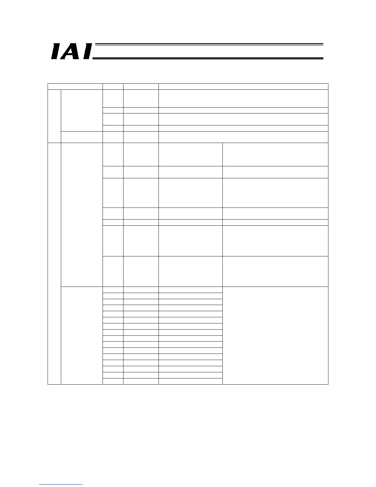
Signal type Bit Signal name Description
15 MON
When this signal is ON (“1”), control outputs from the PLC are effective
(outputs from the PLC are reflected in the controller unit). When the signal
is OFF (“0”), the outputs are ineffective.
14 - Cannot be used. Always keep this signal OFF (0).
13 RTE
When ERR-T or ERR-C is occurred, it can be cancelled by setting this bit
to 1 (level input) from the current condition.
Control signal 0
12-0 - Cannot be used. Always keep this signal OFF (0).
PLC output
Control signal 1 15-0 - Cannot be used.
15 RUN
Gateway unit operation
normal output
This signal is ON while the gateway unit is
operating normally. The signal is
synchronized with the LED (RUN) on the front
panel of the unit.
14 LERC -
If ERR-C occurs, the current condition is
maintained.
13 ERRT
ROBONET communication
error output
This signal turns ON upon detection of a
ROBONET communication (SIO
communication) error. The signal is
synchronized with the ERROR-T LED on the
front panel of the unit.
12 MOD MODE switch output
This signal is ON when the MODE switch on
the front panel of the unit is set to MANU.
11-10 - - Cannot be used.
9 W8B16
8 W8B8
7 W8B4
6 W8B2
5 W8B1
Number-of-axes setting in
direct numerical
specification mode
The number of axes in the direct numerical
specification mode is output as a 5-bit binary
code.
4 W4B16
3 W4B8
2 W4B4
1 W4B2
Status signal 0
0 W4B1
Positioner mode or simple
direct mode
The number of axes in the positioner mode or
simple direct mode is output as a 5-bit binary
code.
15 LNK15 Linked axis No. 15
14 LNK14 14
13 LNK13 13
12 LNK12 12
11 LNK11 11
10 LNK10 10
9 LNK9 9
8 LNK8 8
7 LNK7 7
6 LNK6 6
5 LNK5 5
4 LNK4 4
3 LNK3 3
2 LNK2 2
1 LNK1 1
PLC input
Status signal 1
0 LNK0 0
The signal of each linked axis turns ON (“1”).

 Loading...


