Model 250
Printer Applicator
Operators/Technical Manual Section Two
Section 2 Page 1 of 14
Section Two
Component Location and Identification
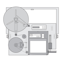
2.1 Identification of the 250 components
Table 2-1 250 Label Applicator Parts Identification Front and Back View
Reference
Number
Part Name or Function
1 Low Label Sensor
2 U-arm
3 Electrical Module
4 Pneumatics Module
5 Area of Printer Placement
6 Tamp Cylinder Mounting Bolts
7 Air Connection for Tamp Vacuum
8 Tamp Vacuum Chamber
9 Tamp Pad
10 Air Assist Mounting
11 Low Label Sensor Wand
12 12.5” Unwind Flange
13 Brake Band Mounting
14 Unwind Mounting Block
15 U-arm Mounting Block
16 Dancer Arm
17 Rewind Flange
18 Rewind Motor
19 Label Web Path
20 U-arm Mounting Bolts
21 Idler Roller
22 Printer Mounting Holes
23 U-arm Mounting Hole, to mount U-arm to Raising Mechanism
24 LCD screen for Applicator Functions and Operations
25 Selection Buttons for Applicator Operations and Functions
26 Gauges (3) for Visual View of Air Pressures in System
27 Face Plate
28 Air Cylinder, Tamp Module
29 Air Cylinder Tamp Module Mounting Block
30 Tamp Pad Mounting Plate