Model 250
Printer Applicator
Operators/Technical Manual Section Two
Section 2 Page 4 of 14
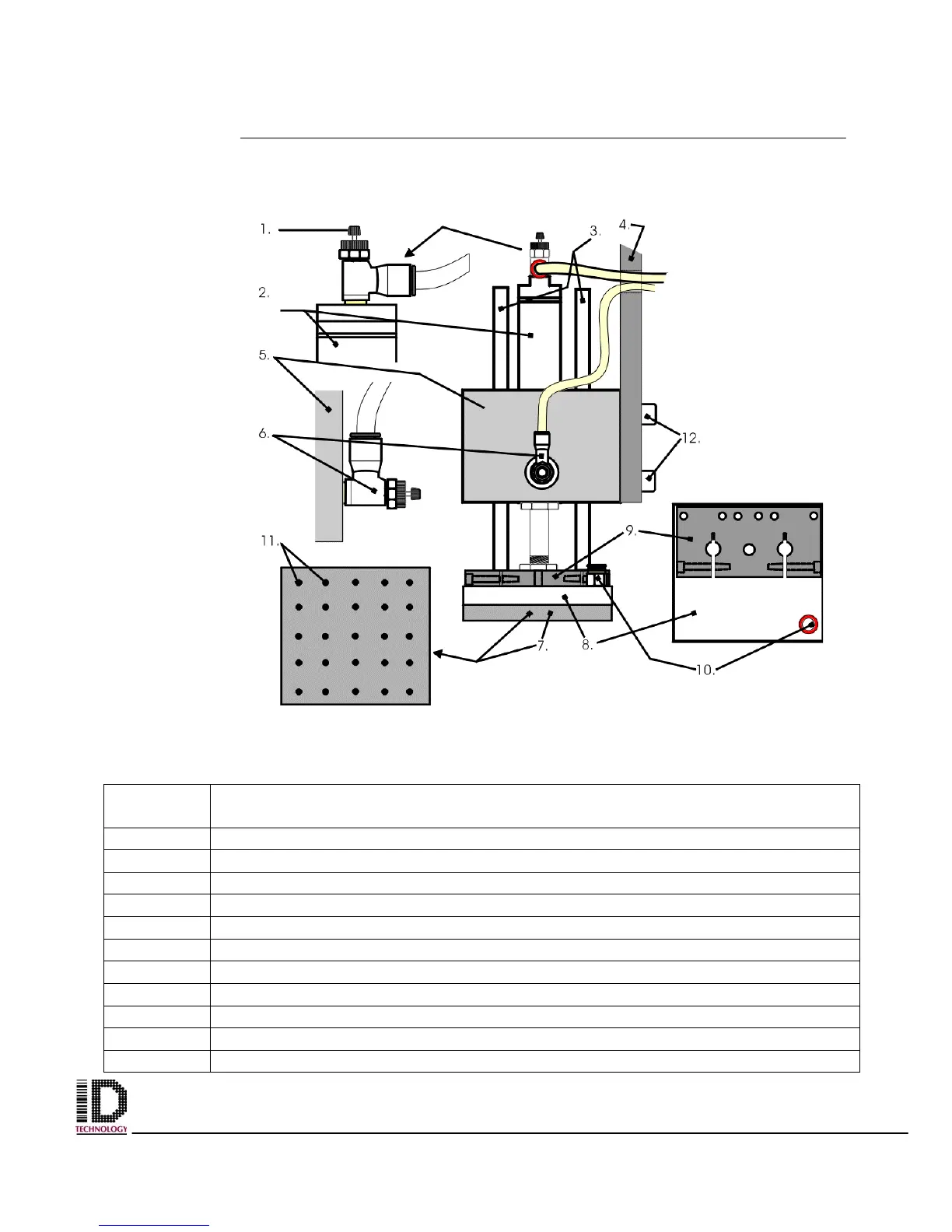
Tamp Module
Table 2-2 Tamp Module Parts Identification
Reference
Number
Part Name / Identification Function
1 Flow Adjustment / Air Hose Connection, Cylinder Extend
2 Air Cylinder
3 Cylinder Guide Rods
4 Face Plate
5 Tamp Module Mounting Block
6 Flow Control / Air Hose Connection, Cylinder Retract
7 Tamp Pad
8 Tamp Pad Block / Vacuum Chamber
9 Tamp Pad Mounting Bracket
10 Air Hose Connection, Vacuum for Tamp Pad
11 Vacuum Pad Vacuum Holes
Figure 2-3 Tamp Assembly