Model 250
Printer Applicator
Operators/Technical Manual Section 3A
Section 3A Page 3 of 9
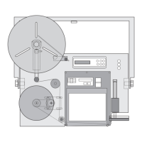
Remove all connectors from the Electronics
Module of the 250. That would include the
product detector, Flashing Beacon, Printer
Connector and Status Output amphenol.
Ensure power is off and remove cable.
Ensure power plug is removed from the
electronics module. (See Fig. 3A-3)
Disconnect Plant Air from the unit’s air filter
connection. (See Fig. 3A-4)
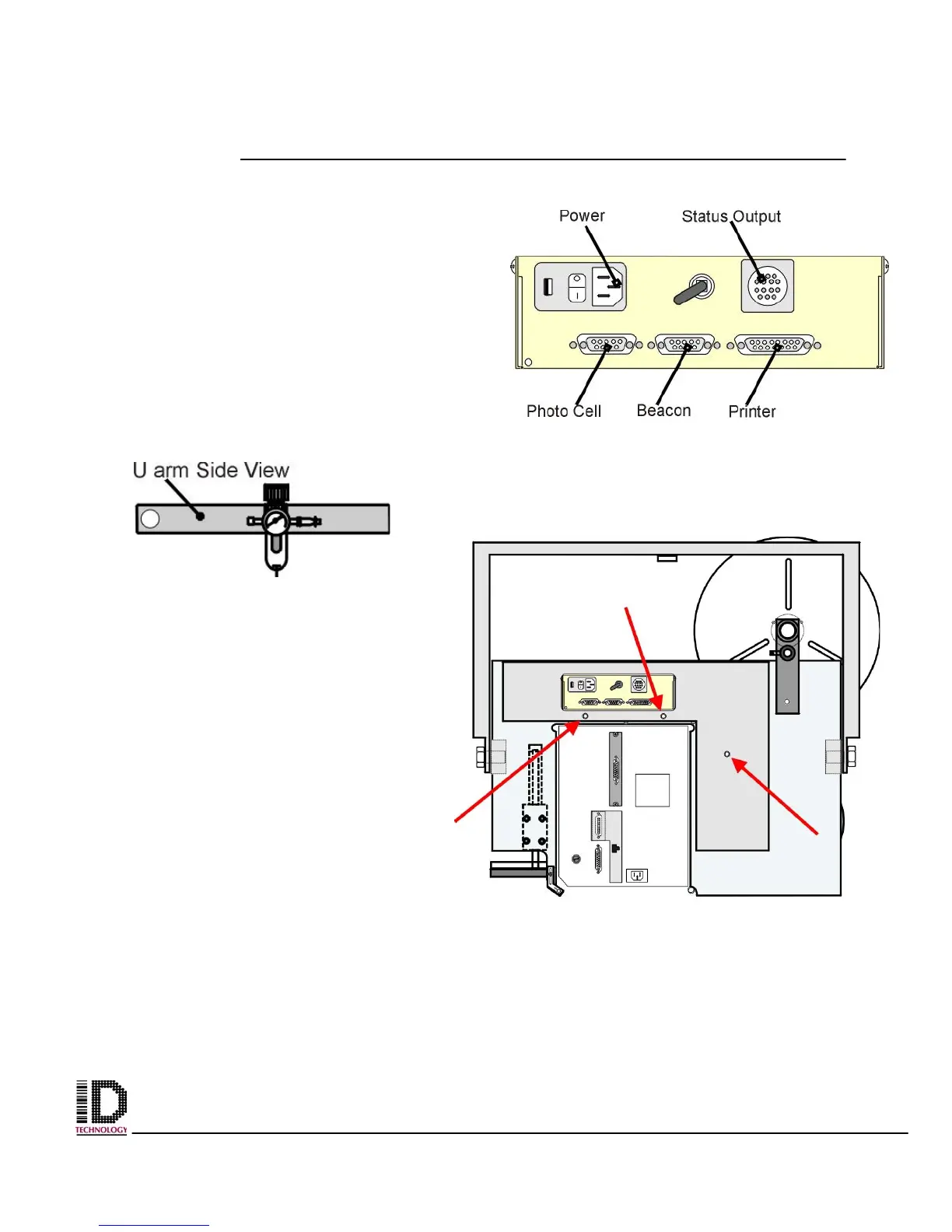
Remove the back cover of the
applicator. Using an M4 Allen wrench,
remove the three bolts from the back
cover and set aside. These bolts will be
needed to re-install the cover.
The locations of the bolts are pointed
out in Fig. 3A-5 with the arrows. The
cover is held in place with only the
three bolts so; after the last bolt is
removed the cover will fall. Ensure you
have a hand holding the cover in place.
Set the cover aside at this time.
Figure 3A-5 Location of Back Cover
mounting bolts
Figure 3A-3 Electronics Module, Back
View, Connector Identification.
Figure 3A-4 Location of Air
Filter on U-arm