Model 250
Printer Applicator
Operators/Technical Manual Section Three
Section 3 Page 3 of 19
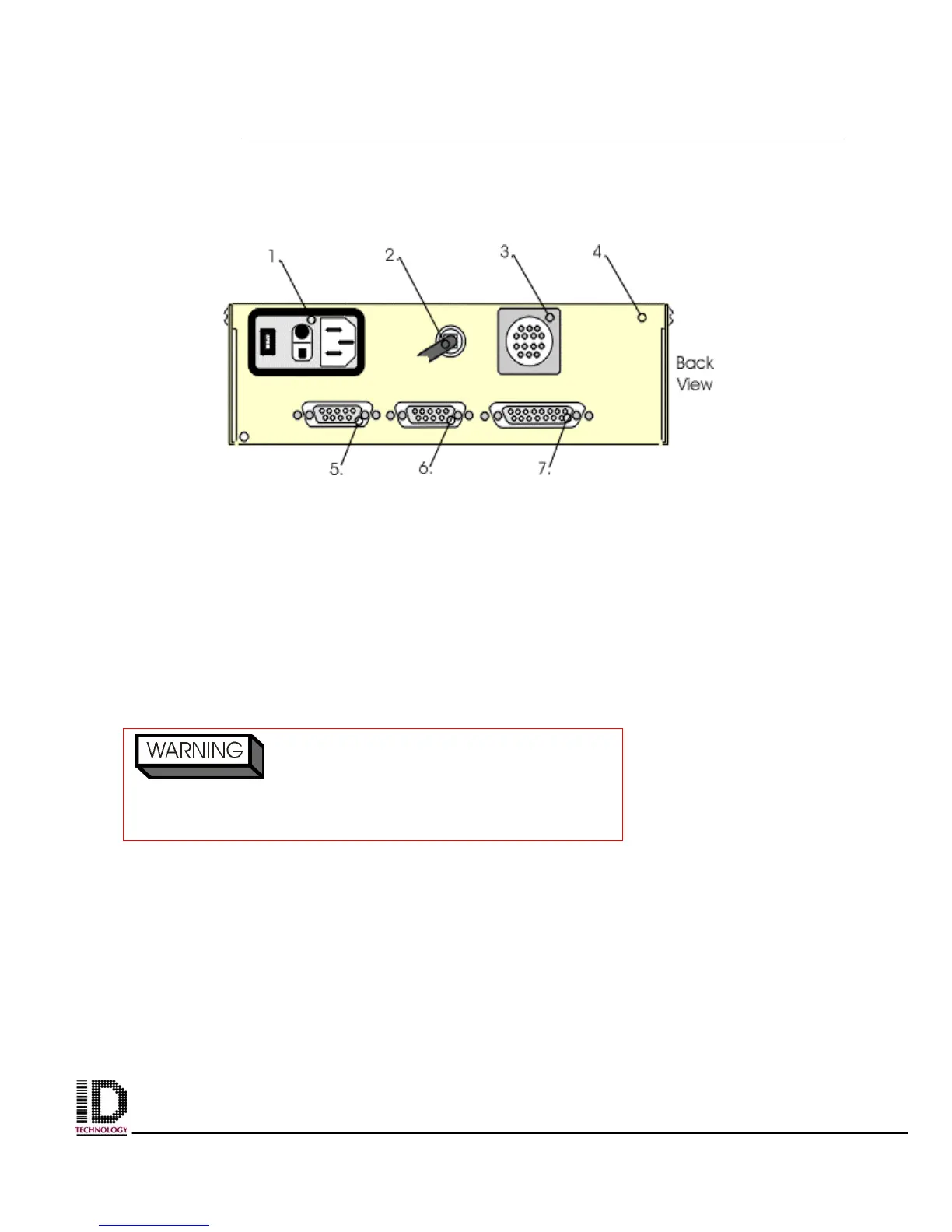
Once the printer is mounted onto the faceplate make the following connections to the
back of the applicators electrical panel. (ref # 4, figure 3 -6);
Main Power In: On the back of the electrical panel will be a cable ending in a three-
pronged plug. This is the applicator power cord. (ref # 2, figure 3-6) Connect this plug to
plant power.
Printer: (Recommend a UPS power source.) Connect power cable from back of print
engine to the electrical panel reference #1. (ref #1, figure 3 –6)
16-pin female connector (ref # 3 figure 3 –6) - connector for the system status output
9-pin female connector (ref #5, figure 3 – 6) - connector for the photocell
9-pin female connector (ref #6, figure 3 – 6) - connector for the status beacon
15-pin female connector (ref #7, figure 3 – 6) - connector for a printer
Ensure the power rating on the applicato
matches the power on the plant power rating.
Example: 110V AC 60 Hz to 110V AC 60 Hz
Figure 3-6 Back Panel of the Electrical Module