Model 250
Printer Applicator
Operators/Technical Manual Section Three
Section 3 Page 2 of 19
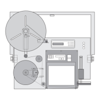
Figure 3-4 Print engine mounting
hole placement on faceplate.
If your OEM print engine came in a separate
carton from the applicator:
Locate the print engine, remove the packing and
carefully take engine out of carton. Locate the five
bolts that mount the engine to the faceplate. If
they are in the faceplate remove them and set
aside. Slide the engine into the area on the
faceplate and align the mounting holes on the
engine with those on the faceplate. Start each bolt
by hand and ensure all five line up and engage
without cross threading. Once all bolts have been
started, using a 4 mm Allen wrench tighten
securely.
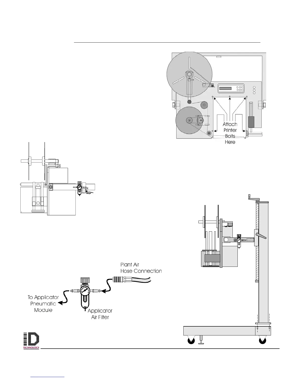
Locate the plant air
hose connection. The
applicator requires
clean dry air at 80 psi to 120 psi. A pre filter upstream of the
applicator will reduce required preventive maintenance on the
system. The connector should be a ¼ NPT. Connect to the
applicator Air Filter located on the u-arm. (See figure 3-5).
Connect the plant air hose to
the input of the air filter. The
output of the air filter will be
connected to the pneumatic
manifold block on the
pneumatics module mounted
on the back of the applicator
faceplate.
End View
Tamp Down
Orientation
Figure 3-5 Air Filter
placement on U-arm and