Model 250
Printer Applicator
Operators/Technical Manual Section Four
Section 4 Page 3 of 6
1.
2.
2.
2.
3.
3.
4.
5.
5a.
5.
1.
6.
7.
7.
8.
9.
10.
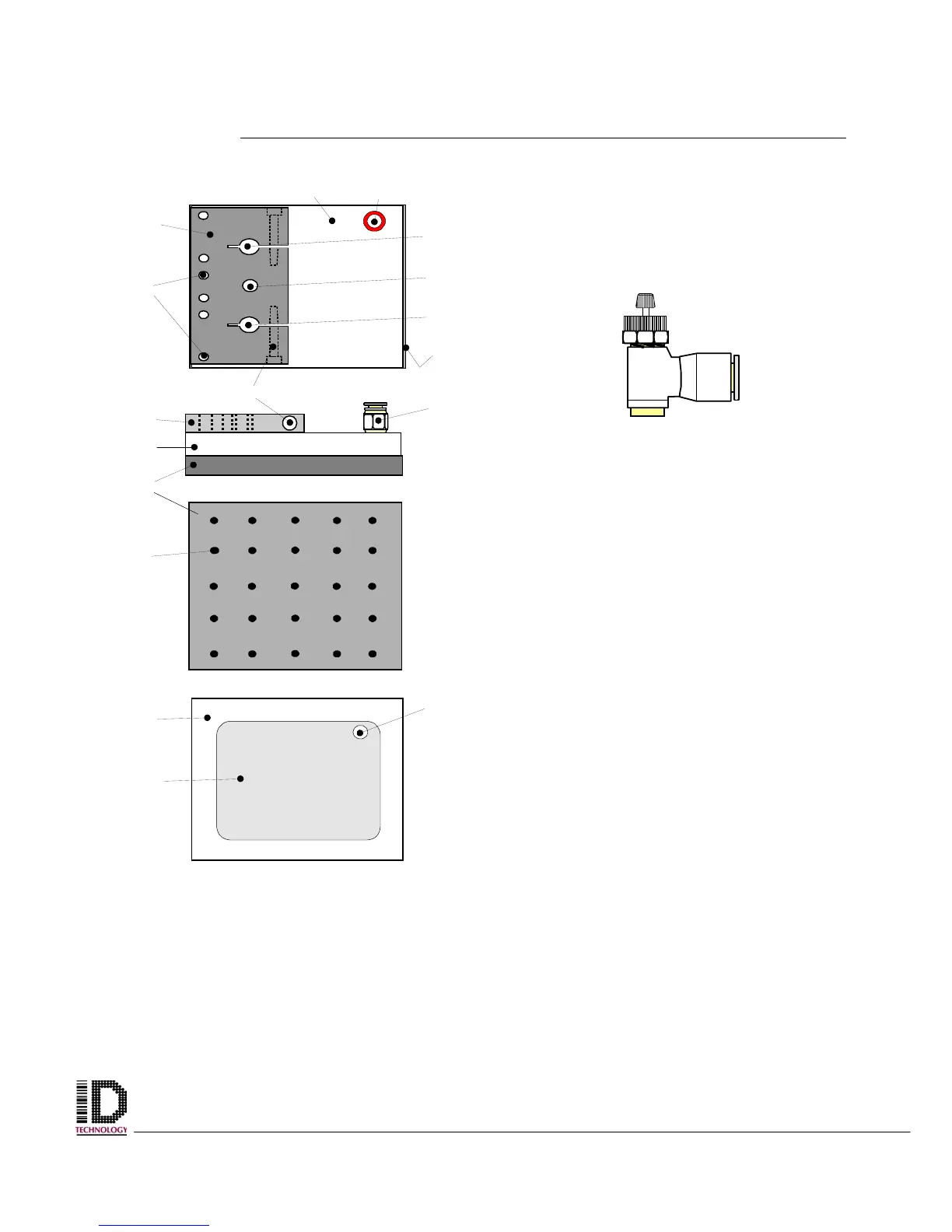
Figure 4-4 Flow Control Valve located
on top and on front of air cylinder
Figure 4-5 Tamp Pad Assembly (top view on top, front view under
that, then tamp pad- bottom view, and last, tamp pad mounting block /
vacuum chamber - bottom view with out tamp pad mounted)