Model 250
Printer Applicator
Operators/Technical Manual Section Two
Section 2 Page 8 of 14
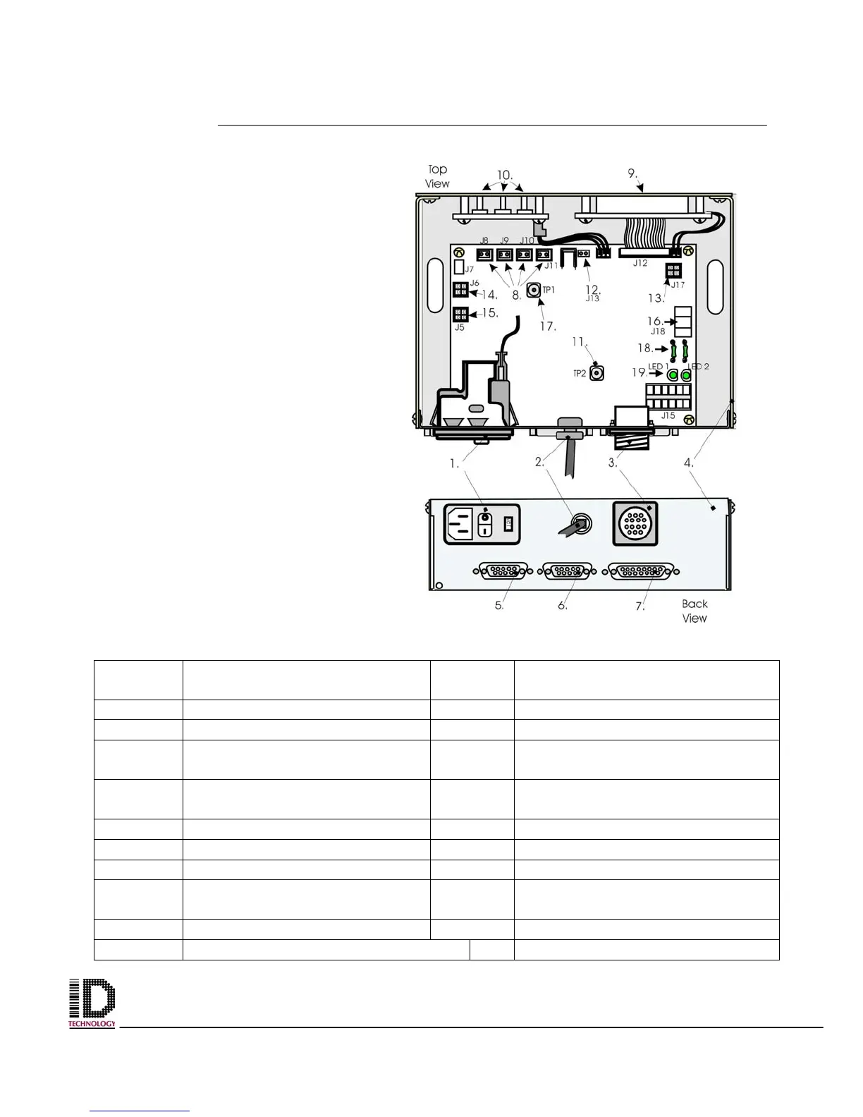
Electronics Module
Located on the back panel and held
on by four bolts. The power supply is
located underneath the module and
attached with standoffs.
Table 2-6 Electronics Module Parts Identification
Reference
Number
Part Name / Function
Reference
Number
Part Name / Function
1 Power Input Module 2 Power In Cable
3 14 Pin (Status Output Conn.) 4 Electronics Module Housing
5 9 Pin (Photo Cell Connector) 6 9 Pin (Flashing Beacon
connector)
7 15 Pin Connection from Printer 8 Pneumatic Connections
(J8,9,&10)
9 LCD Window 10 Operator Input Function Keys
11 Ground Connector 12 Rewind Motor Connection (J13)
13 Low Label Connection (J17) 14 Smart Tamp (J6)
15 Tamp Home Connection (J5) 16 5V, GND, 24V from Power
Supply
17 GND Connector TP1 18 Fuse (plug in)
19 Led 1 and 2 (Blown fuse detection)
Figure 2-7 Electronics Module