Model 250
Printer Applicator
Operators/Technical Manual Section Three
Section 3 Page 7 of 19
widths of media that can be used. (Please refer to the print engine manual for an
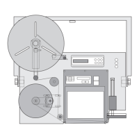
explanation on adjusting these guides.) In figure 3-12 the item marked as #1 is a spring
loaded bar that holds the web flat. It is equipped with a roller for reducing pull. You must
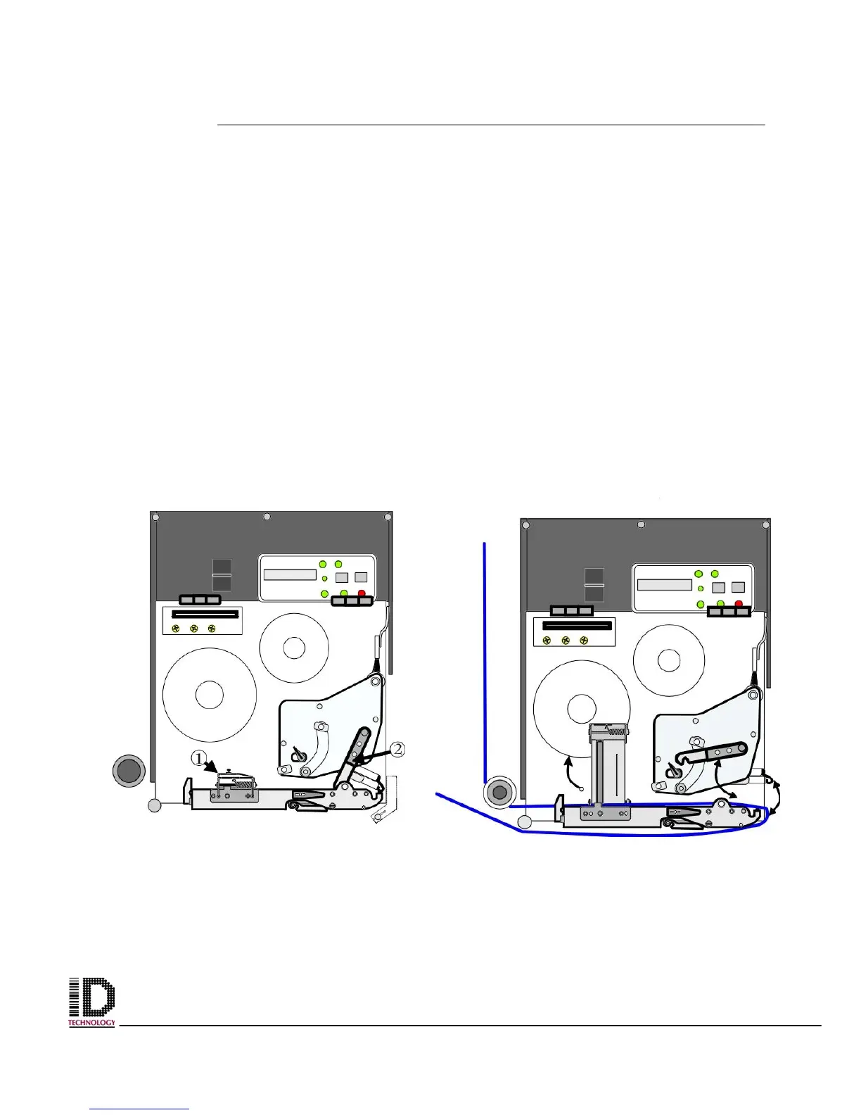
disengage this mechanism to thread the web. Figure 3-13 shows the mechanism
unlatched and in the raised or open position. (Please refer to the print engine manual for
a better explanation on how to unlatch this mechanism.) Item marked as #2, in figure 3-
12, is a lever that can be shifted to the left. Shifting this lever causes the print head to
spring up. The web must be threaded under the print head, out the far right side of the
engine and back under to the left. Figure 3-13 shows the print head in the “up” or “open”
position. (Referring to the print engines operator’s manual will give a clear understanding
of the operation and procedures for moving, adjusting, and locking the print head.)
It will be a lot easier to thread the liner if you remove the label from the web prior to
threading over the air assist tube. When bringing the web back under the print engine
ensure that the liner is above the air assist tube. (Liner should be between the air assist
tube and print engine.) Take the web to the rewind spindle, remove the locking pin, and
wrap the liner clockwise around the shaft. Reinstall the locking pin onto the shaft catching
the liner between the tines and the shaft.
Figure 3-12 Print Engine with door
removed for clarity.
Figure 3-13 Print Engine with label
web shown threaded
.