AFL-xxx-9103 Panel PC
Page 55
NOTE:
When purchasing the arm please ensure that it is VESA compliant and
that the arm has the correct interface pad. If the mounting arm is not
VESA compliant it cannot be used to support the AFL-xxx-9103.
Step 2: Once the mounting arm has been firmly attached to the surface, lift the flat panel
PC onto the interface pad of the mounting arm.
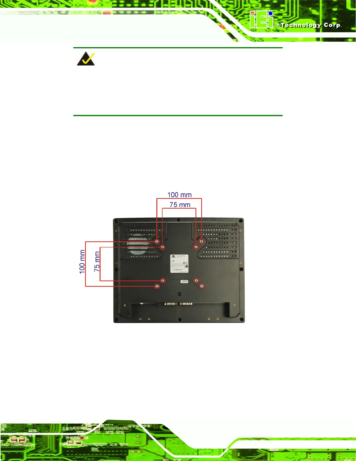
Step 3: Align the retention screw holes on the mounting arm interface with those in the
flat panel PC. The AFL-xxx-9103 arm mount retention screw holes are shown in
Figure 3-11.
Figure 3-11: Arm Mounting Screw Holes
Step 4: Secure the flat panel PC to the interface pad by inserting four retention screws
through the bottom of the mounting arm interface pad and into the flat panel
PC.Step 0:
 Loading...