AFL-xxx-9103 Panel PC
Page 60
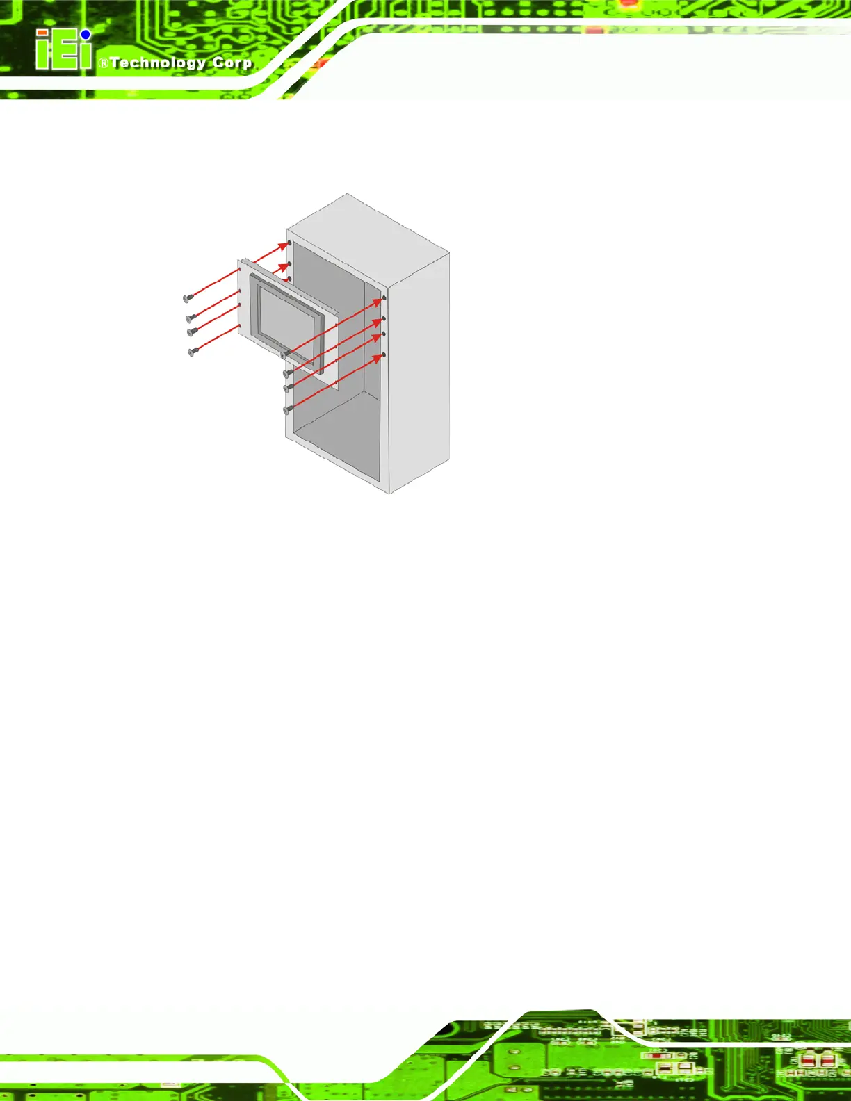
Step 4: Slide the flat panel PC with the attached rack/cabinet bracket into a rack or
cabinet (
Figure 3-17).
Figure 3-17: Install into a Rack/Cabinet
Step 5: Once the flat panel PC with the attached rack/cabinet bracket has been properly
inserted into the rack or cabinet, secure the front of the rack/cabinet bracket to
the front of the rack or cabinet (
Figure 3-17).Step 0:
3.9 Bottom Panel Connectors
3.9.1 LAN Connection
There are two external RJ-45 LAN connectors. The RJ-45 connectors enable connection
to an external network. To connect a LAN cable with an RJ-45 connector, please follow
the instructions below.
Step 1: Locate the RJ-45 connectors on the bottom panel of the AFL-xxx-9103 Series.
Step 2: Align the connectors. Align the RJ-45 connector on the LAN cable with one of
the RJ-45 connectors on the bottom panel of the AFL-xxx-9103. See
Figure 3-18.
 Loading...