AFL-xxx-9103 Panel PC
Page 62
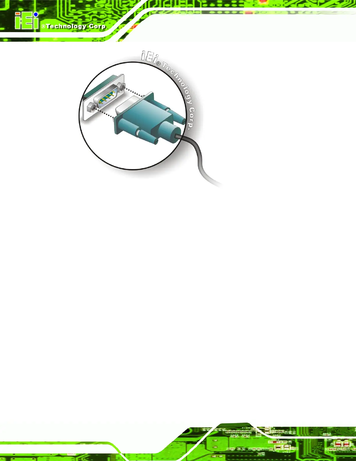
Figure 3-19: Serial Device Connector
Step 3: Secure the connector. Secure the serial device connector to the external
interface by tightening the two retention screws on either side of the connector.
Step 0:
3.9.3 USB Device Connection
There are four external USB 2.0 connectors. All connectors are perpendicular to the
AFL-xxx-9103. To connect a USB 2.0 or USB 1.1 device, please follow the instructions
below.
Step 1: Located the USB connectors. The locations of the USB connectors are shown
in Chapter 2.
Step 2: Align the connectors. Align the USB device connector with one of the
connectors on the bottom panel. See
Figure 3-20.
 Loading...