EMBEDDED Intel486™ PROCESSOR HARDWARE REFERENCE MANUAL
7-4
The dynamic bus sizing feature of Intel486 processor is significantly different than that of the
Intel386™ DX processor. The Intel486 processor requires that the data bytes be driven on the ad-
dressed lines only, unlike the Intel386 DX processor, which expects both high and low order
bytes on D15–D0. The simplest example of this function is a 32-bit aligned BS16# read. When
the Intel486 processor reads the two higher order bytes, they must be driven on D31–D16 data
bus, and it expects the two low order bytes on D15–D0. The Intel386 DX processor always reads
or writes data on the lower 16-bits of the data bus when BS16# is asserted.
The external system design must provide buffers to allow the Intel486 processor to read or write
data on the appropriate data bus pins. Table 7-2 shows the data bus lines where the Intel486 pro-
cessor expects valid data to be returned for each valid combination of byte enables and bus sizing
options. Valid data is driven only on data bus pins which correspond to byte enable signals that
are active during write cycles. Other data pins are also driven, but they do not contain valid data.
Unlike the Intel386 DX processor, the Intel486 processor does not duplicate write data on the data
bus when corresponding byte enables are deasserted.
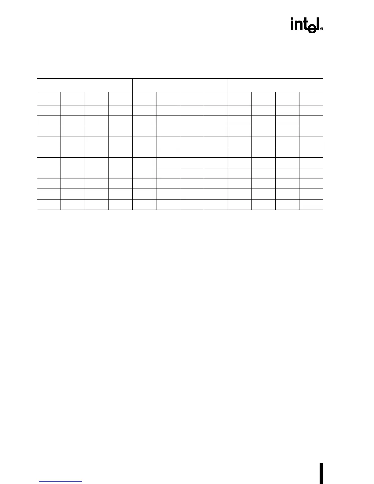
Table 7-1. Next Byte-Enable Values for the BS
x
# Cycles
Current Next with BS8# Next with BS16#
BE3# BE2# BE1# BE0# BE3# BE2# BE1# BE0# BE3# BE2# BE1# BE0#
1 1 1 0NNNNNNNN
11001101NNNN
100010011011
000000010011
1 1 0 1NNNNNNNN
100110111011
000100110011
1 0 1 1NNNNNNNN
00110111NNNN
0 1 1 1NNNNNNNN
NOTE: “N” means that another bus cycle is not required to satisfy the request.